Lens barrel

a technology of lens barrel and barrel body, which is applied in the field of lens barrel, can solve the problems of difficult to achieve further reduction of the size of the lens barrel, the bulkiness of the actuator, and the size of the actuator

Inactive Publication Date: 2011-06-30
PANASONIC CORP
View PDF12 Cites 19 Cited by
  • Summary
  • Abstract
  • Description
  • Claims
  • Application Information

AI Technical Summary

Problems solved by technology

A problem with the sensor shift method, however, is that the actuators are bulkier than with an optical method in which blur correction is performed by moving a correction lens.
Furthermore, since the imaging element requires numerous signal lines, it must be driven ...

Method used


Image

  • Lens barrel
  • Lens barrel
  • Lens barrel

Examples


first embodiment

1: Overview of Digital Camera

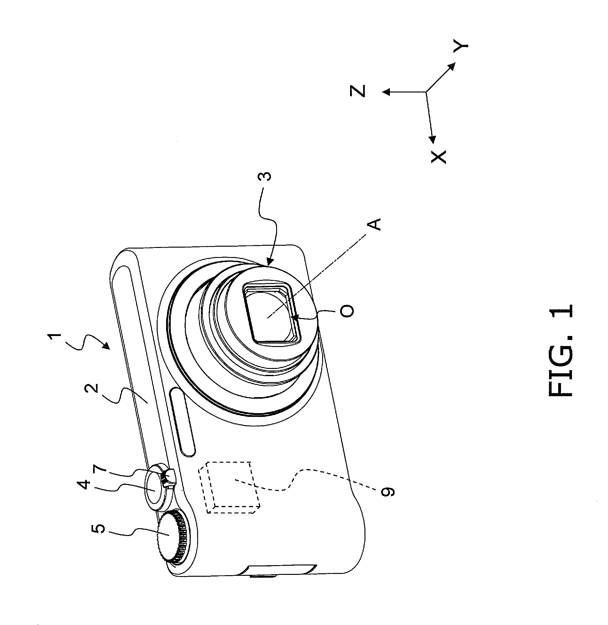
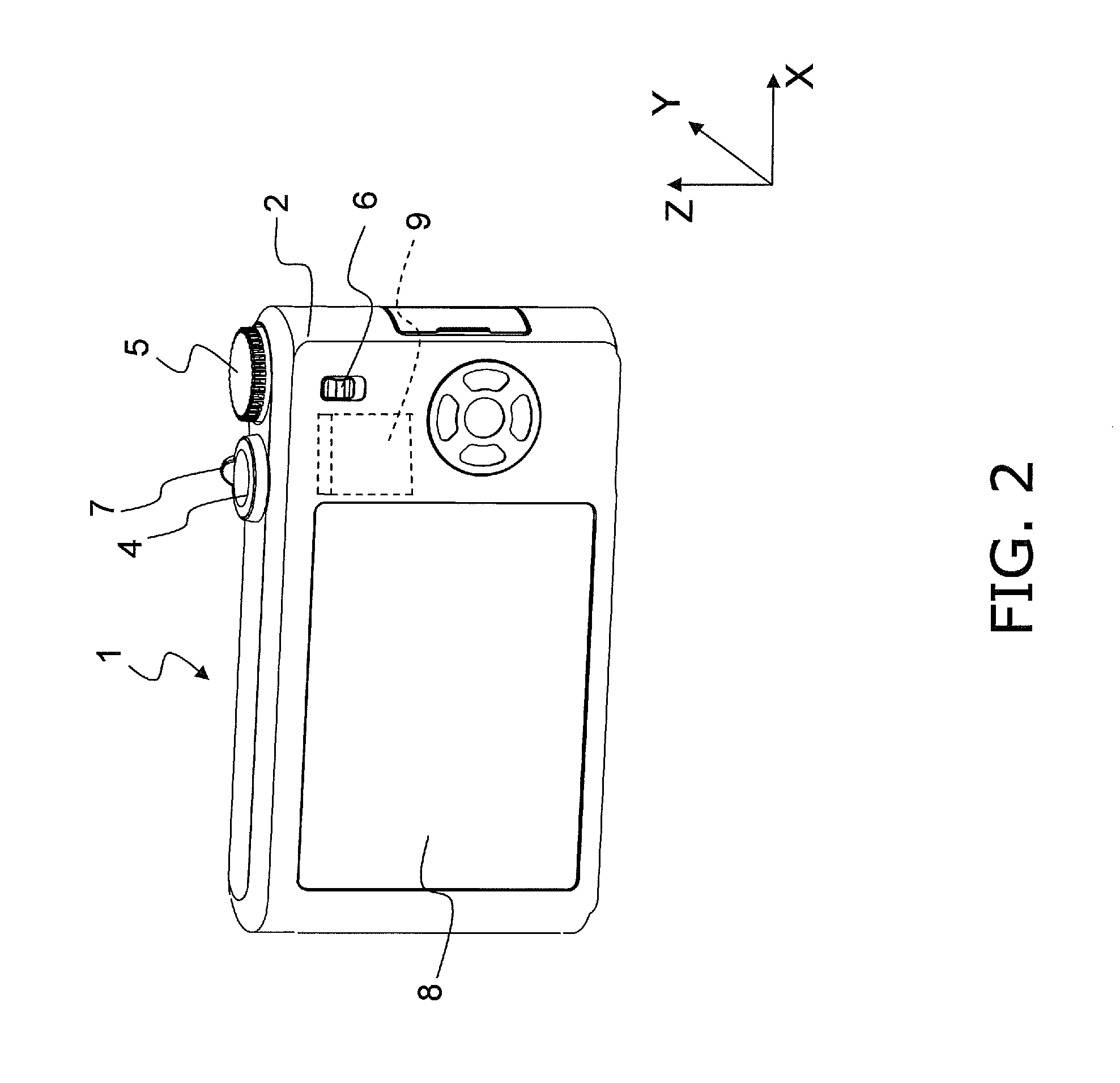
[0054]A digital camera 1 will be described through reference to FIGS. 1 and 2. FIGS. 1 and 2 are simplified oblique views of the digital camera 1. FIG. 1 shows the case when a lens barrel 3 is in its imaging state (wide angle end).

[0055]The “wide angle end” referred to here indicates a state in which the focal length of an optical system O (discussed below) is at its shortest, and the “telephoto end” indicates a state in which the focal length of the optical system O is at its longest. A state when the power is on is defined as an imaging state, and a state in which the lens barrel 3 is at its shortest length with the power off is defined as a stowed state. In this embodiment, the imaging state corresponds to the wide angle end state of the optical system O.

[0056]The digital camera 1 is a camera used to acquire an image of a subject. A multi-stage telescoping lens barrel 3 is installed in the digital camera 1 in order to afford a higher zoom ratio and re...

second embodiment

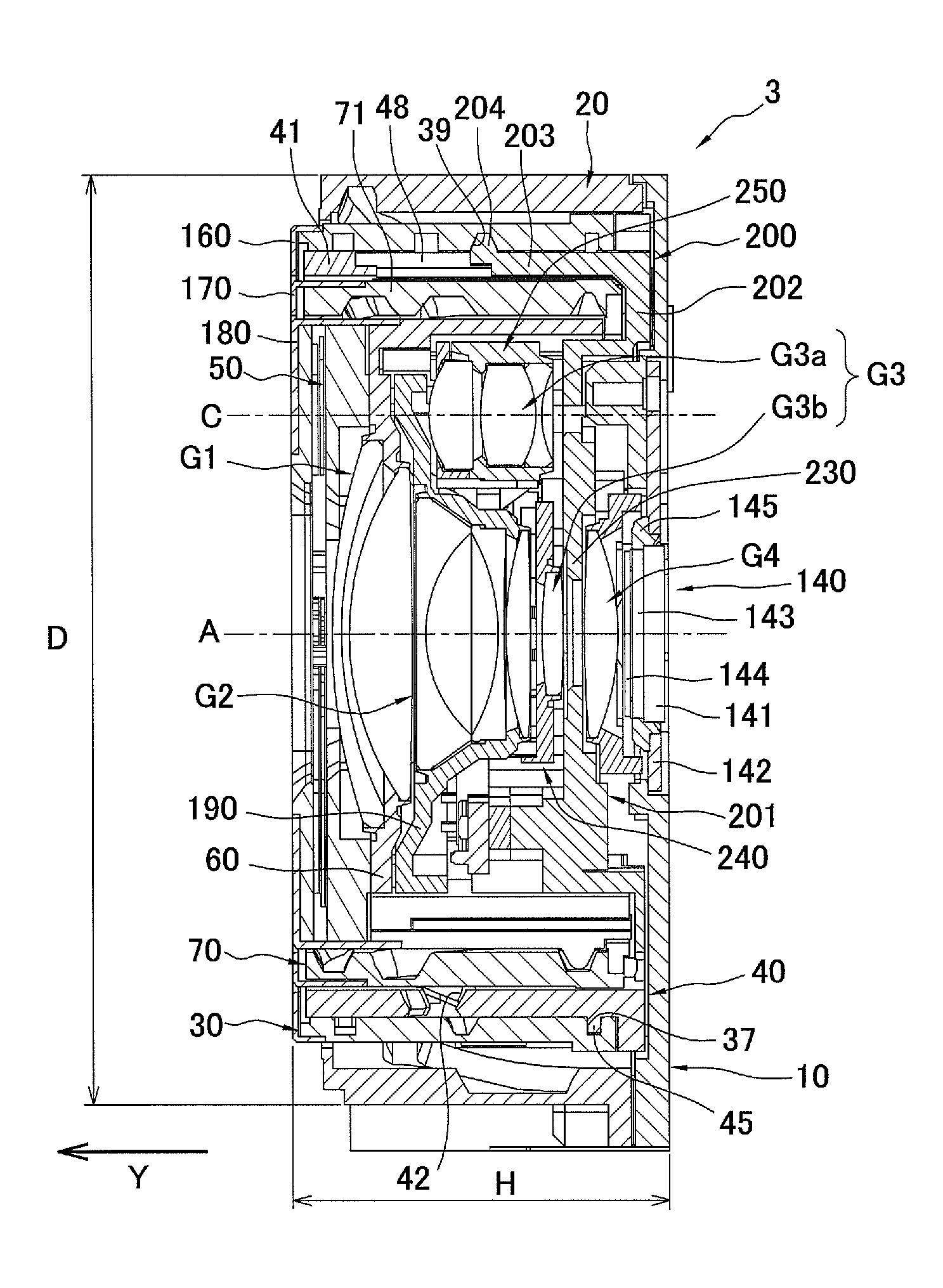
[0222]In the first embodiment above, the retractable lens frame 250 is retracted to avoid the second lens frame 190, but when the diameter of the second lens group G2 is large, the retractable lens frame 250 protrudes far outward in the radial direction, and this can make it harder to reduce the size of the lens barrel 3 in the radial direction.

[0223]In view of this, a constitution is possible in which the second lens group G2 is retracted in addition to the retractable lens group G3a. A lens barrel 303 pertaining to the second embodiment will now be described through reference to FIGS. 24 to 33B.

[0224]Those components having substantially the same function as the components in the first embodiment above will be numbered the same, and will not be described in detail again.

1: Configuration of Lens Barrel

[0225]As shown in FIGS. 24 to 28, the lens barrel 303 comprises the optical system O, the fixed frame 20, the zoom motor unit 110, the master flange 10, the drive frame 30, the camera...


PUM


Abstract

A lens barrel which includes an optical system, a support mechanism, a drive correcting mechanism, a retractable lens frame, and a drive retracting mechanism. The optical system includes a corrective lens group and a retractable lens group. The support mechanism movably supports the corrective lens group in a direction perpendicular to the optical axis of the optical system. The drive correcting mechanism is configured to drives the support mechanism so that the corrective lens group moves in a direction perpendicular to the optical axis of the optical system. The retractable lens frame retractably supports the retractable lens group to a first position in which the optical axis of the retractable lens group is offset from the optical axis of the optical system. The drive retracting mechanism is configured to drive the retractable lens frame so that the retractable lens group retracts to the first position.

Description

CROSS-REFERENCE TO RELATED APPLICATIONS[0001]This application claims priority under 35 U.S.C. §119 to Japanese Patent Application No. 2009-297791, filed on Dec. 28, 2009 and Japanese Patent Application No. 2010-254006, filed on Nov. 12, 2010. The entire disclosure of Japanese Patent Application No. 2009-297791 and Japanese Patent Application No. 2010-254006 are hereby incorporated herein by reference.BACKGROUND[0002]1. Technical Field[0003]The technology disclosed herein relates to a lens barrel.[0004]2. Background Information[0005]In recent years, we have witnessed the growing popularity of digital cameras that make use of a Charge Coupled Device (CCD) or Complementary Metal-Oxide Semiconductor (CMOS) sensor or other such imaging element to convert an optical image into an electrical signal, and digitally record this electrical signal.[0006]With a digital camera such as this, there is a need not only for a higher pixel count in the CCD or CMOS sensor, but also for higher performanc...

Claims


Application Information

Patent Timeline
IPC IPC(8): G03B17/00
CPCG02B7/102G03B5/00G03B2205/0015G03B17/12G03B17/04
Inventor HONSHO, HIRONORIONISHI, HIDEO
Owner PANASONIC CORP
Why Eureka
Try Eureka