Molded auxetic mesh

a technology of auxetic mesh and mesh, which is applied in the field of molded auxetic mesh, can solve the problems of overlapping parts of the mesh, affecting the appearance of the mesh, and affecting the effect of the mesh,

Inactive Publication Date: 2011-06-30
3M INNOVATIVE PROPERTIES CO
View PDF41 Cites 36 Cited by
  • Summary
  • Abstract
  • Description
  • Claims
  • Application Information

AI Technical Summary

Benefits of technology

[0009]“comprises (or comprising)” means its definition as is standard in patent terminology, being an open-ended term that is generally synonymous with “includes”, “having”, or “containing”. Although “comprises”, “includes”, “having”, and “containing” and variations thereof are commonly-...

Problems solved by technology

The different sized openings in conventional molded meshes may be considered unsightl...

Method used


Image

  • Molded auxetic mesh
  • Molded auxetic mesh
  • Molded auxetic mesh

Examples


examples

[0036]Cell Size Determination

[0037]Auxetic mesh cell size was determined using defined diameter rods that were mounted in a fixture to facilitate measurement of the open spaces or cells. The probe rods ranged in diameter from 0.0254 cm (centimeter) to 0.5334 cm, in 0.0254 cm increments. The cell size was measured by selecting the maximum size probe that fit into the cell without causing distortion of the cell shape prior to placement of the probe. This size was recorded, and the next cell size was measured and recorded until all cells contained within the molded mesh were measured and the cells tallied at each probe size.

[0038]Auxetic Mesh Formation Apparatus and Process

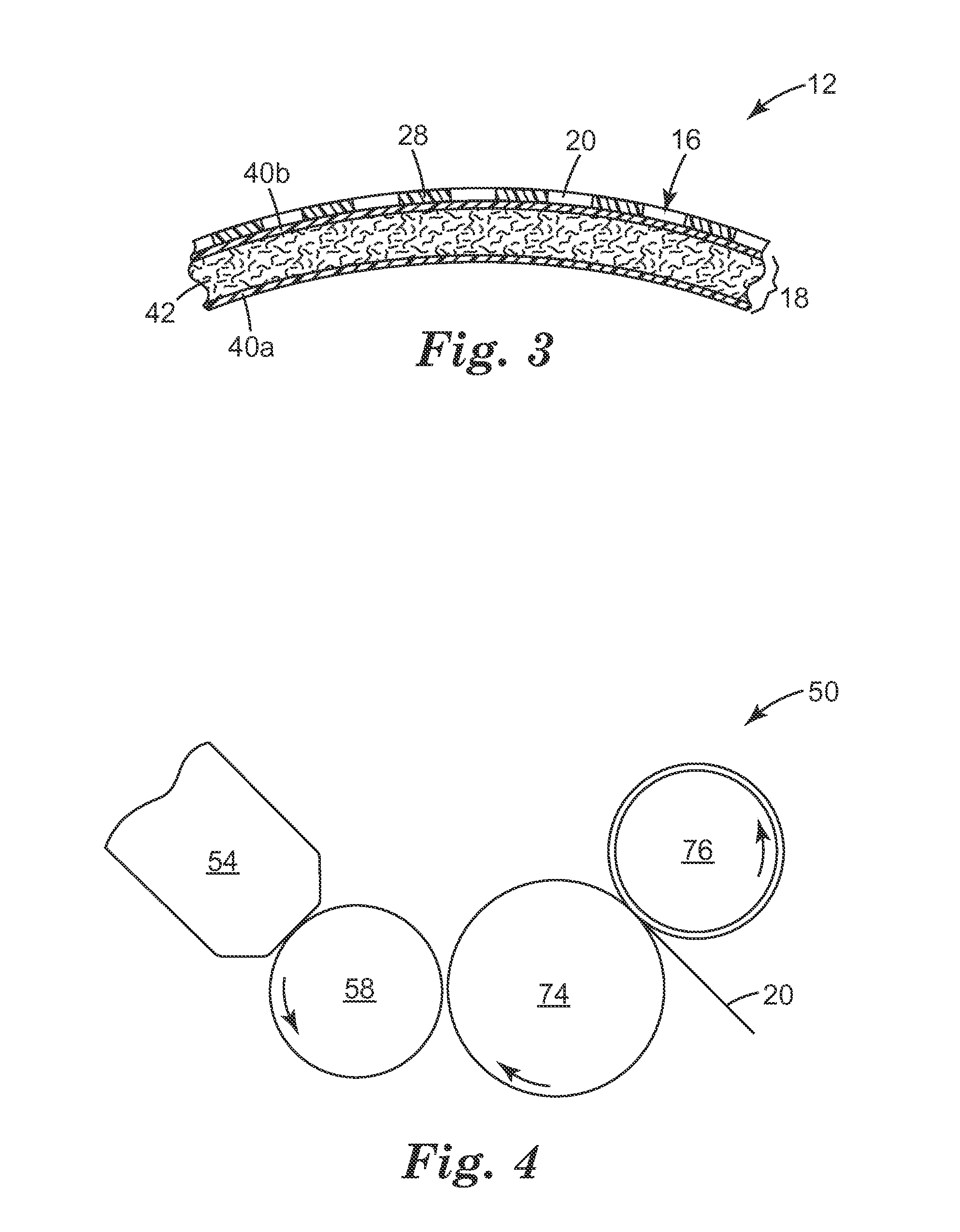
[0039]An auxetic web was produced using a system 50 that resembles the apparatus shown in FIG. 4. A 40 mm diameter twin-screw extruder was fitted with a gear pump and was used to deliver a molten polymer blend at melt temperature of approximately 246° C. to a slot die 54, at an extrusion rate of 1.43 kg / hr / cm (kilogr...


PUM

PropertyMeasurementUnit
Thicknessaaaaaaaaaa
Angleaaaaaaaaaa
Areaaaaaaaaaaa

Abstract

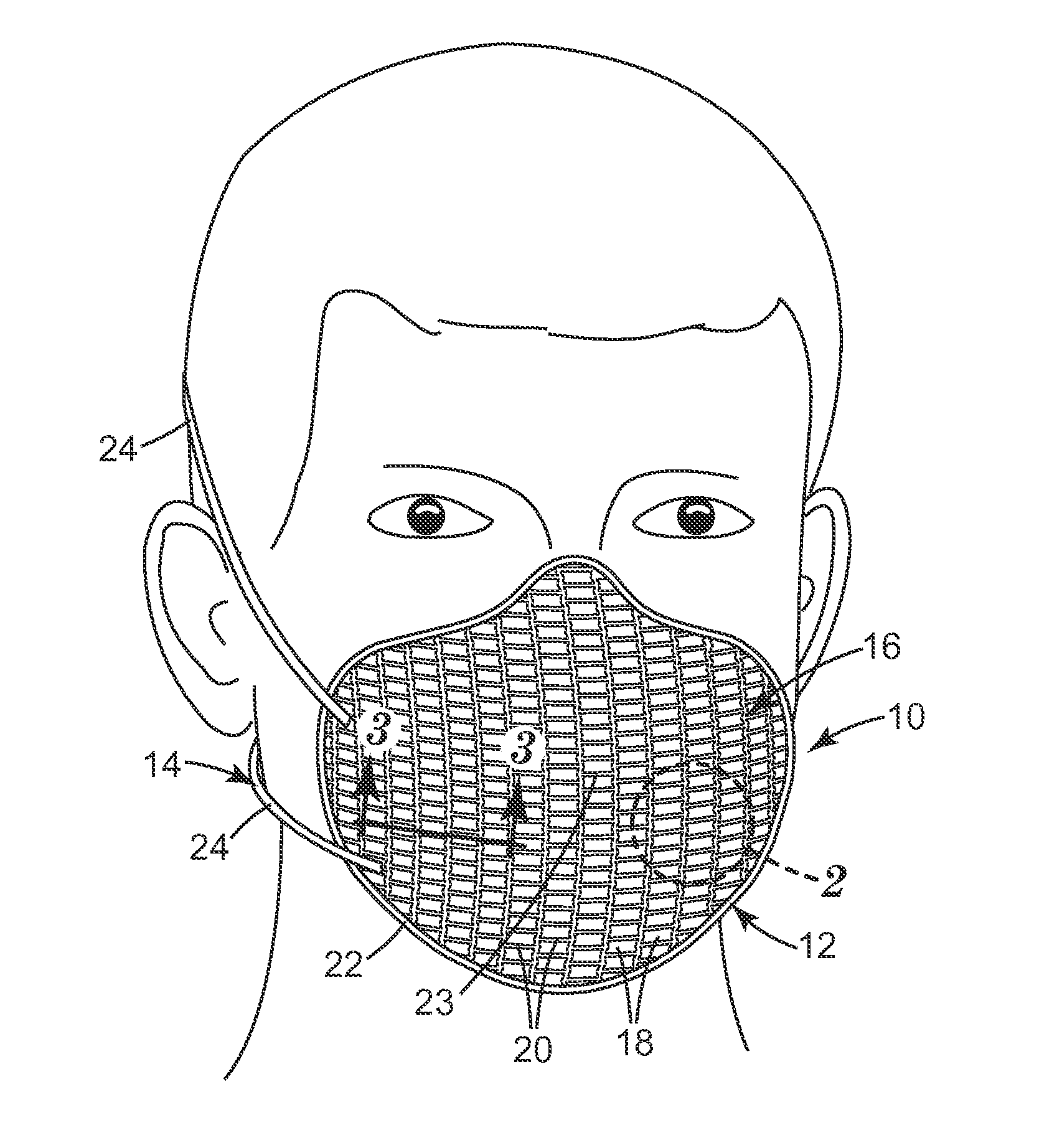
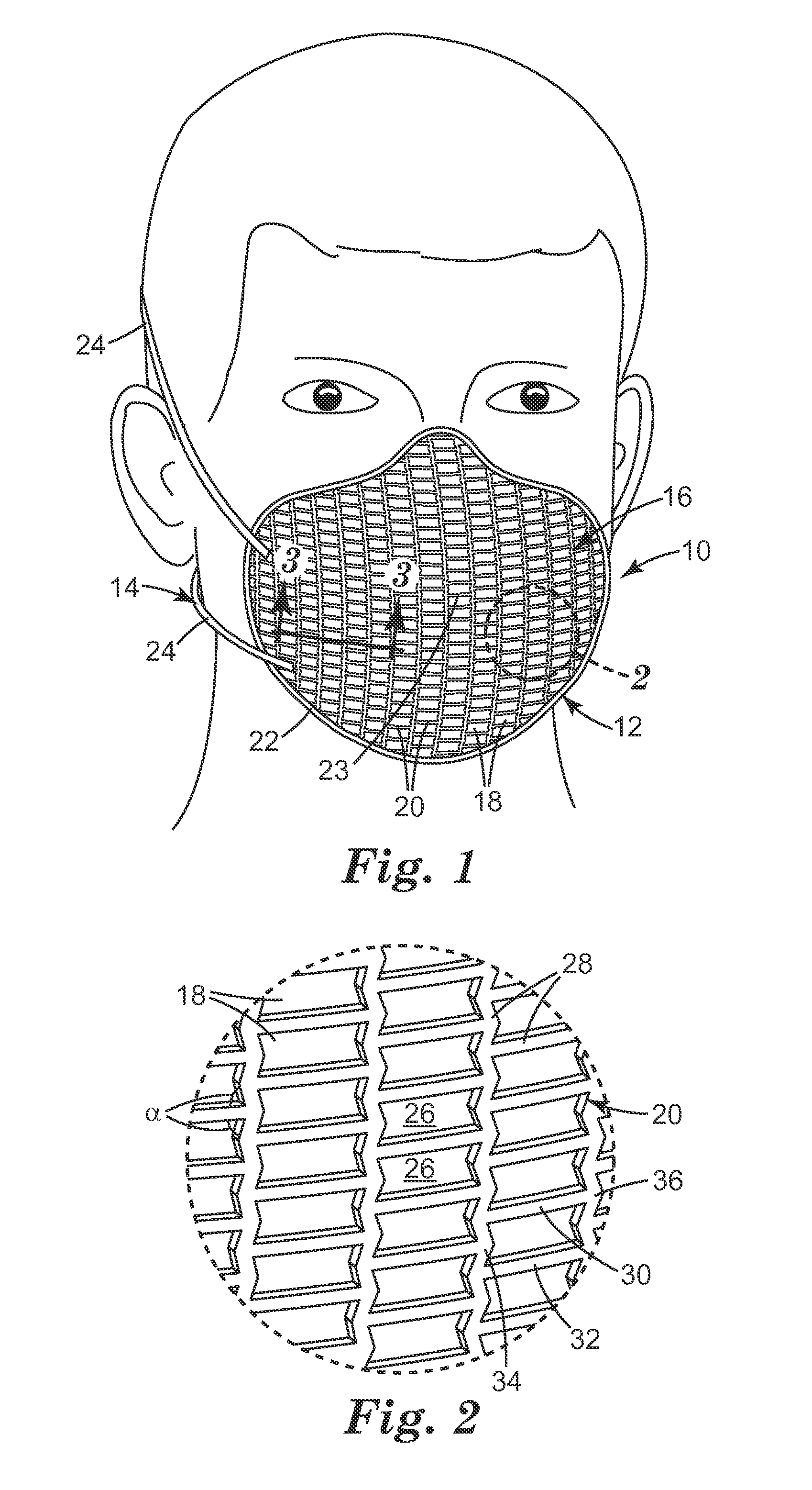
An article that comprises an auxetic mesh 20 that has been molded into an intended shape. Molded auxetic articles do not distort as much as convention meshes when subjected to the heat and pressure of a molding operation.

Description

CROSS-REFERENCE TO RELATED APPLICATION[0001]This application claims the benefit of U.S. Provisional Patent Application No. 61 / 291,057, filed Dec. 30, 2009.[0002]The present invention pertains to a molded auxetic mesh and to a method of making such a mesh.BACKGROUND[0003]Auxetic materials have been made by a variety of methods, including etching, printing, die cutting, and laser cutting. Examples of various patent publications that describe auxetic articles and their methods of production include U.S. Pat. No. 6,878,320B1 to Alderson et al., U.S. 2005 / 0142331A1 to Anderson et al., U.S. 2005 / 0159066A1 to Alderson et al., U.S. 2005 / 0287371A1 to Chaudhari et al., U.S. 2006 / 0129227A1 to Hengelmolen, U.S. 2006 / 0180505A1 to Alderson et al., U.S. 2006 / 0202492A1 to Barvosa-Carter et al., U.S. 2007 / 0031667A1 to Hook et al. EP1,165,865B1 to Alderson, WO91 / 01210 to Evans et al., WO91 / 01186 to Ernest et al., WO99 / 22838 to Alderson et al., WO99 / 25530 to Lakes et al., WO00 / 53830 to Alderson et al....

Claims


Application Information

Patent Timeline
IPC IPC(8): B32B3/24B29C43/02
CPCA62B18/025B29C43/003B29K2105/0854B32B3/266B32B27/12B29L2031/14B29L2031/753B29K2995/0094B29L2028/00B29L2031/4835A41D13/1146Y10T442/10A62B23/025B32B5/022B32B5/028B32B5/26B32B2262/0253B32B2571/00B32B2535/00A41D13/11
Inventor MARTIN, PHILIP G.
Owner 3M INNOVATIVE PROPERTIES CO
Why Eureka
Try Eureka