Al technical title is built by PatSnap Al team. It summarizes the technical point description of the patent document.
a spinal fusion and system technology, applied in the field of systems and methods for spinal fusion, can solve the problems of loss of control of treatment devices or implants, short hospital stays, and minimally-invasive techniques
Inactive Publication Date: 2011-06-30
BAXANO
View PDF110 Cites 191 Cited by
Summary
Abstract
Description
Claims
Application Information
AI Technical Summary
This helps you quickly interpret patents by identifying the three key elements:
Problems solved by technology
Method used
Benefits of technology
[0020]Also described herein are devices and methods for implanting and anchoring an electrical lead. An electrical lead may be used to help treat chronic pain. The devices and methods described herein may allow precise implantation and anchoring of a lead. Adequate anchoring of implants (such as leads) is critical to prevent migration and eventual failure of these devices.
[0051]Described below are particular examples, including devices adapted for use with these examples that illustrate methods of performing such treatments and therapies. For example, described herein are methods of performing a spinal fusion. In some embodiments, a spinal decompression procedure may also be performed, since it may enhance success rates of the spinal fusion procedure.
[0059]Also described herein are particular examples, including devices adapted for use with these examples that illustrate methods of performing treatments and therapies including spinal fusion surgery, in particular a less invasive posterior column fusion or soft fusion, such as by way of an interspinous fusion or spinous process fixation. Additionally, facet joint fixation may also be performed, either bilaterally or unilaterally. In some embodiments, a spinal decompression procedure may also be performed, since it may enhance success rates of the spinal fusion procedure.
[0097]In some embodiments, the first fixation plate further includes a slot sized and configured to receive a portion of the rod when the rod is pivoted with respect to the fixation plate such that the rod is not perpendicular to the plate. In some embodiments, the second fixation plate is configured to be deployed from a first lateral side of a spinous process and to couple to the first lateral side of a spinous process and wherein the first fixation plate is configured to be deployed from the first lateral side of a spinous process and to couple to the second opposite lateral side of the spinous process. In some embodiments, at least one of the first and the second fixation plate further includes a coupling member disposed on the inside face of the fixation plate, wherein the coupling member of the inside face are configured to couple to the first or second lateral side of the spinous process. In some embodiments, the coupling member includes at least one protrusion sized and configured to dig into or catch onto bone thereby aiding in the coupling of the fixation plate to the spinous process.
Problems solved by technology
This may result in shorter hospital stays, or allow outpatient treatment.
Unfortunately, the use of minimally-invasive techniques has often required a loss in control of the treatment device or implant, as the treatment sites are often deep within the body, proving both difficult to access, as well as difficult to manipulate the device when the body region is minimally invasively accessed.
In particular, finding leverage to position or manipulate minimally invasive devices once deployed has proven extremely difficult.
As a result, complex and expensive tools have been created to allow manipulation of distally-positioned devices or implants within the body.
Even in variations of minimally invasive procedures in which a second access port is used, coordination of the two access ports at the target has proven difficult, particularly when one or more devices are inserted through different access ports and required to meet at an internal site.
Finally, manipulation of implants and devices using any of these minimally invasive techniques has also proven difficult.
For example, when treating small or enclosed body regions such as joints, or regions surrounded by sensitive non-target tissue, manipulation of a device or implant within this space has been limited by the ability to control the distal end of the device from a proximal position.
This may lead to undesirable and dangerous kinking, bending, and torqueing of the access device and / or implant.
There are many disadvantages to conventional spinal fusion surgery.
In some cases, the muscles can scar to one another and thereby lose independent function.
Furthermore, in some cases there can be a loss of innervations and / or sensation.
Method used
Image
Click on the blue label to locate the original text in one second.
Reading with bidirectional positioning of images and text.
Examples
Embodiment Construction
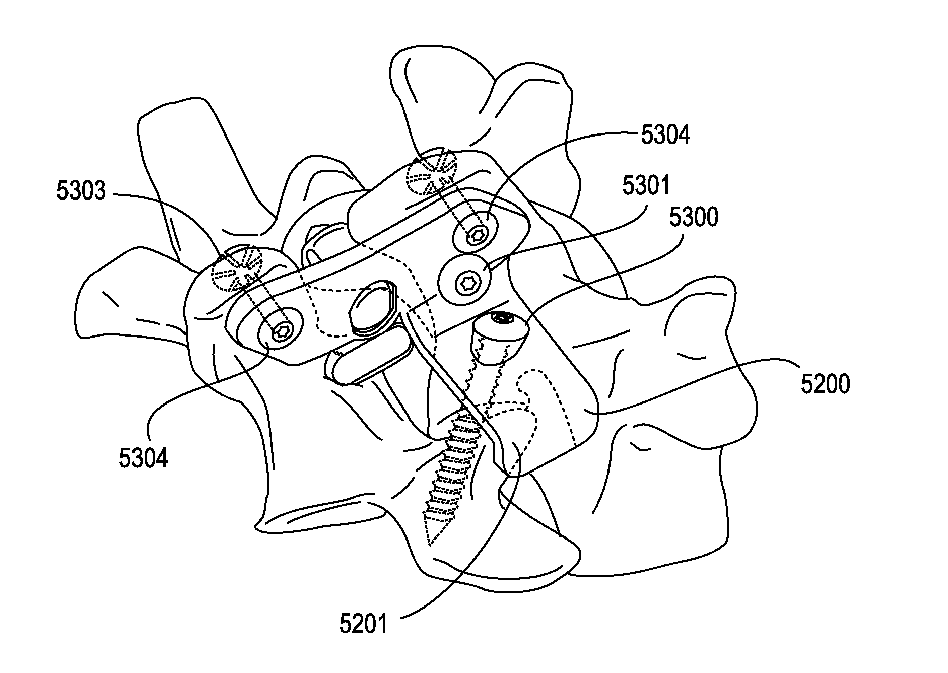
[0178]The systems, methods and devices described herein are generally applicable and adapted for use in treating the spine. Although numerous variations of systems, methods and types of devices for treating the spine are described may be used in one or more spinal procedure without requiring or reference to other aspects of the methods, systems and devices described herein, it is intended that many of the features illustrated may be adapted for use, and / or combined with, one or more features, steps or entire devices or methods described.
[0179]For example, some of the devices, systems and methods described herein are adapted for bimanual use, while other devices, systems and methods are adapted for unimanual use. Simialrly, some of the devices, methods and systems described herein are adapted for unilateral insertion / removal, while other devices, methods and systems are adapted for bilateral operation.
[0180]Thus, in some variations of the devices, systems and methods for treating tis...
PUM
Abstract
Described herein are methods, devices and systems for performing an interspinous fusion, in particular for performing an interspinous fusion unilaterally. In general an interspinous fusion system may include a first fixation plate configured to couple to a first lateral side of a spinous process, a rod extending from the first fixation plate at a joint such that the rod is pivotable with respect to the first fixation plate, and a second fixation plate configured to couple to a second lateral side of a spinous process opposite from the first fixation plate. In general, a method of performing an interspinous fusion unilaterally may include the steps of placing a first fixation plate, having a rod extending from the fixation plate, between two adjacent spinous processes from a fist lateral side of the spinous processes, pivoting the rod with respect to the first fixation plate such that the plate abuts the second, opposite, lateral side of at least one of the spinous processes, and placing a second fixation plate such that it abuts the fist lateral side of at least one of the spinous processes.
Description
CROSS REFERENCE TO RELATED APPLICATIONS[0001]This patent application claims priority to U.S. Provisional Application No. 61 / 290,458, titled “SYSTEMS AND METHODS FOR PERFORMING SPINAL FUSION”, filed on Dec. 28, 2009; U.S. Provisional Application No. 61 / 314,557, titled “TISSUE REMOVAL AND IMPLANT DELIVERY DEVICES, SYSTEMS, AND METHODS”, filed on Mar. 16, 2010; U.S. Provisional Application No. 61 / 318,941, titled “TISSUE REMOVAL AND IMPLANT DELIVERY DEVICES, SYSTEMS, AND METHODS”, filed on Mar. 30, 2010; U.S. Provisional Application No. 61 / 329,563, titled “SYSTEMS AND METHODS FOR PERFORMING SPINAL FUSION”, filed on Apr. 30, 2010; U.S. Provisional Application No. 61 / 350,600, titled “SYSTEMS AND METHODS FOR PERFORMING SPINAL FUSION”, filed on Jun. 2, 2010; U.S. Provisional Application No. 61 / 356,557, titled “SYSTEMS AND METHODS FOR PERFORMING SPINAL FUSION”, filed on Jun. 19, 2010; U.S. Provisional Application No. 61 / 357,529, titled “SYSTEMS AND METHODS FOR PERFORMING SPINAL FUSION”, file...
Claims
Application Information
Patent Timeline
Application Date:The date an application was filed.
Publication Date:The date a patent or application was officially published.
First Publication Date:The earliest publication date of a patent with the same application number.
Issue Date:Publication date of the patent grant document.
PCT Entry Date:The Entry date of PCT National Phase.
Estimated Expiry Date:The statutory expiry date of a patent right according to the Patent Law, and it is the longest term of protection that the patent right can achieve without the termination of the patent right due to other reasons(Term extension factor has been taken into account ).
Invalid Date:Actual expiry date is based on effective date or publication date of legal transaction data of invalid patent.
Patent Type & Authority Applications(United States)