
Reusable thin film particle sensor

a technology of thin film and sensor, which is applied in the field of reusable thin film particle sensor, can solve the problems of inconvenient use, inconvenient use, and high cost of flow cytometer equipmen

Inactive Publication Date: 2011-07-07
ORFLO TECH LLC
View PDF54 Cites 20 Cited by
  • Summary
  • Abstract
  • Description
  • Claims
  • Application Information

AI Technical Summary

Benefits of technology

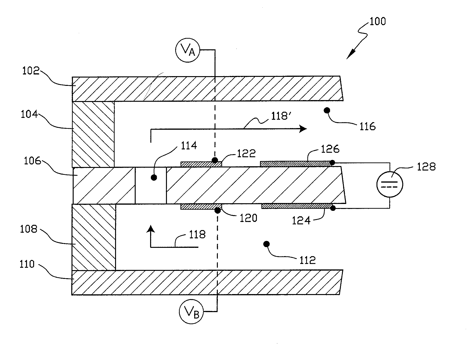
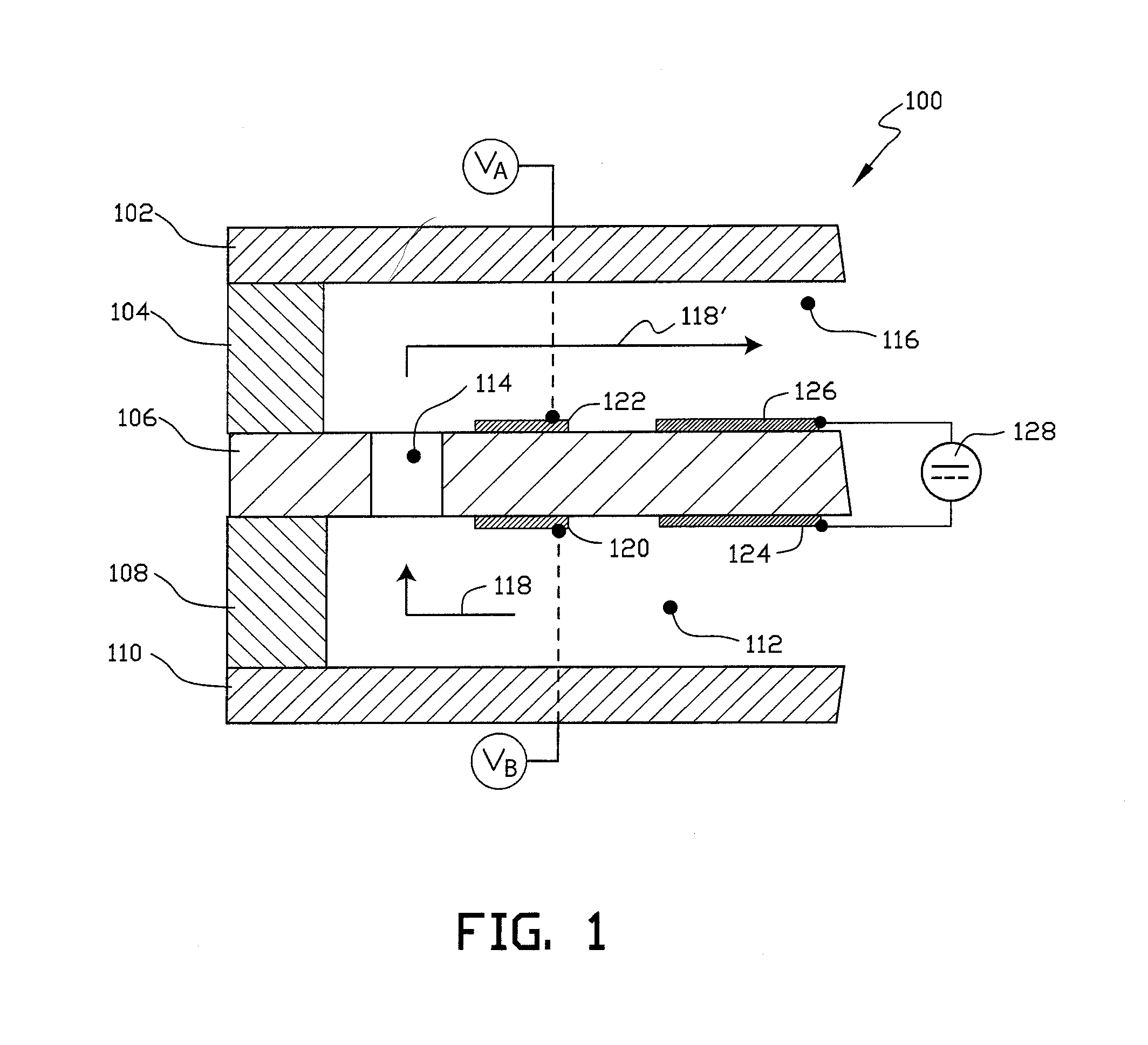
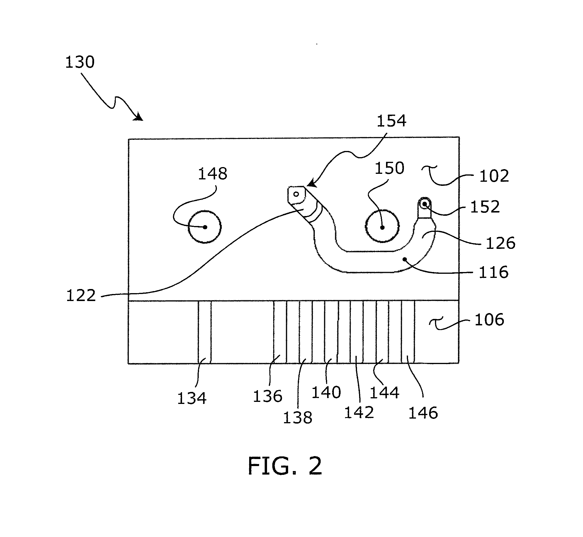
[0023]The manufacturing method may further include the step of forming a plurality of alignment holes in penetration through the interrogation layer and disposed with sufficient precision relative to the second fluid-flow channel such that installation of two of the alignment holes in registration with respective locating pins of a cooperatingly structured interrogation device is effective to dispose the second fluid-flow channel at an interrogation location of the interrogation device within an accuracy of about 50 μm.
[0025]The method may further include forming a plurality of alignment holes in penetration through the interrogation layer and disposed with sufficient precision relative to the fifth fluid-flow channel such that installation of two alignment holes in registration with respective locating pins of a cooperatingly structured interrogation device is effective to dispose the fifth fluid-flow channel at an interrogation location of the interrogation device within an accuracy of about 50 μm.

Problems solved by technology

Unfortunately, flow cytometers are undesirably complex and expensive pieces of equipment.

Method used


Image

  • Reusable thin film particle sensor
  • Reusable thin film particle sensor
  • Reusable thin film particle sensor

Examples


embodiment 130

[0082]An electrical property at an electrode may be monitored to determine arrival of fluid at that electrode. For example, the impedance measured at an electrode undergoes a significant change in value as the wave-front, or the leading edge, an electrolyte fluid passes over the electrode. In one currently preferred use of the sensor component 130 (see FIG. 4), a stimulus electric signal (such as a 1 kHz square wave) is applied to electrode 164. A sudden change in the impedance values measured at electrodes 166 and 168 indicates the successive arrivals of the wave-front of the sample fluid at each respective electrode. In the illustrated embodiment 130, first verification of fluid at electrode 166 ensures that sample fluid is in place for interrogation, and a test run can begin. Feedback from electrode 166 may therefore serve as a first trigger to begin interrogation of the fluid sample.

[0083]A change in impedance at electrode 168 indicates the wave-front has reached that electrode ...

embodiment 280

[0111]A schematic illustrating a generalized operable arrangement of structure employed in embodiments structured according to certain principles of the invention and enabling optically-based interrogation is indicated generally at 280 in FIG. 20. As illustrated, embodiment 280 includes an opaque member, generally indicated at 282, disposed between a radiation source 284 and a radiation detector 286. At least one orifice 288 is disposed in opaque member 282 to provide a flow path between a first side, generally indicated at 290, and a second side, generally indicated at 292. Orifice 288 may be characterized as having a through-axis 294 extending between the first and second sides 290 and 292 of opaque member 282, respectively.

[0112]Both of the thickness, T1, of an opaque member and characteristic size, D1, of an orifice 288 are typically sized in agreement with a size of a particle of interest to promote single-file travel of the particle through the opaque member, and to have only ...


PUM

PropertyMeasurementUnit
thicknessaaaaaaaaaa
thicknessaaaaaaaaaa
thicknessaaaaaaaaaa

Abstract

A microfluidic sensor formed by stacking a plurality of substantially non-electrically conductive layers, typically formed from thin polymer films. Certain layers may carry patterned electrodes that are arranged to permit their connection to an electrical interrogation circuit. Electrodes may be disposed in a 3-dimensional array in the sensor. A fluid path through the sensor includes an orifice sized to promote single-file travel of particles. The orifice may be defined by a tunnel passing through at least one layer. Particles entrained in an electrolytic carrier fluid may be detected, or otherwise characterized, by interrogation circuitry connected to certain embodiments of the sensor. Sensors generally include portions of a fluid path disposed parallel to the layers. Sensors may operate under the Coulter principle, and / or Stokes' shift phenomena. In certain embodiments, the sensor may be carried by a cartridge, which is adapted to couple with an interrogation platform. In any case, coupling desirably places the sensor in-circuit with operable interrogation structure, as well as with a fluid-flow control device. Structure included in a cartridge may provide fluid sample loading, routing, and storage capabilities.

Description

RELATED APPLICATIONS[0001]This application is a continuation-in-part of U.S. utility application Ser. No. 12 / 381,252, filed Mar. 10, 2009, which is a continuation-in-part of U.S. utility application Ser. No. 11 / 800,167, filed May 4, 2007, now U.S. Pat. No. 7,520,164, and claims the benefit under 35 U.S.C. 119(e) of the filing date of Provisional Application Ser. No. 60 / 798,155, filed May 5, 2006, for “THIN FILM PARTICLE SENSOR”; and is a continuation-in-part of U.S. utility application Ser. No. 12 / 378,757, filed Feb. 19, 2009, which is a continuation-in-part of U.S. utility application Ser. No. 11 / 701,711, filed Feb. 2, 2007, now U.S. Pat. No. 7,515,268, and claims the benefit under 35 U.S.C. 119(e) of the filing date of Provisional Application Ser. No. 60 / 764,697, filed Feb. 2, 2006, for “FLUORESCENCE-ACTIVATED CELL DETECTOR”; and is a continuation-in-part of the International Patent Application filed under the Patent Cooperation Treaty, Serial No. PCT / US2009 / 002172, and claims the...

Claims


Application Information

Patent Timeline
Patent Type & Authority Applications(United States)
IPC IPC(8): G01N15/06B23P17/00
CPCG01N2015/1062B01L2400/0487B01L2300/0874B01L2300/0887G01N15/12G01N2015/1087B01L3/502715B01L2300/0645G01N15/1056G01N15/1463G01N33/49B01L3/502761G01N2015/1037Y10T29/494G01N2015/1019G01N15/1023G01N2015/1024G01N2015/1029G01N15/1433
Inventor AYLIFFE, HAROLD E.
Owner ORFLO TECH LLC
Learn More