System, method and apparatus for tubing connector

Inactive Publication Date: 2011-07-07
SAINT GOBAIN PERFORMANCE PLASTICS CORP
View PDF26 Cites 20 Cited by
  • Summary
  • Abstract
  • Description
  • Claims
  • Application Information

AI Technical Summary

Benefits of technology

[0006]In some embodiments, the retainer has an aspect ratio of approximately 1:1 with respect to the diameter and axial width of the retainer. In other embodiments, the aspect ratio is about 0.7:1 to 1.3:1. A rib may be formed in and substantially circu

Problems solved by technology

Zip ties are inexpensive but form unreliable seals for some applications, and the other types of connectors are more expensive.
In pharmaceutical and medical applications, such tubing connections are often subjected to autoclave environments at elevated temperatures and pressures.
Autoclaves can significantly alter the properties of the materials used to form the tubing, connectors and clamps

Method used


Image

  • System, method and apparatus for tubing connector
  • System, method and apparatus for tubing connector
  • System, method and apparatus for tubing connector

Examples


Embodiment Construction

[0016]Embodiments of a system, method and apparatus for a tubing connector that creates compression between tubing and fittings are disclosed in FIGS. 1-9. For example, some embodiments (see, e.g., FIGS. 1-3) comprise a disposable plastic retainer for clenching and sealing tubing connections with barbed fittings to form an assembly or tubing system.

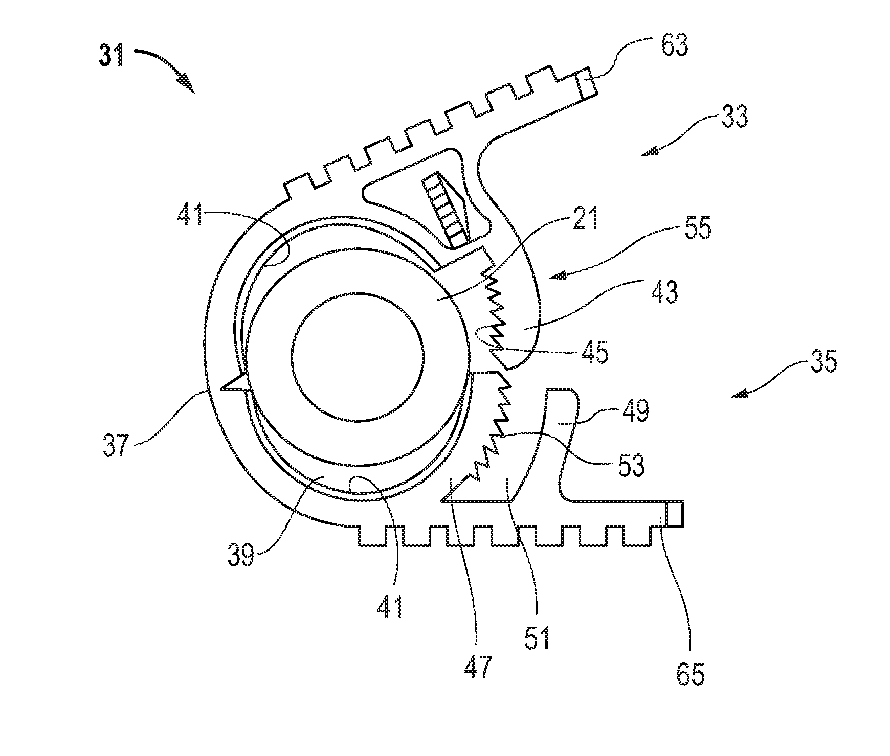
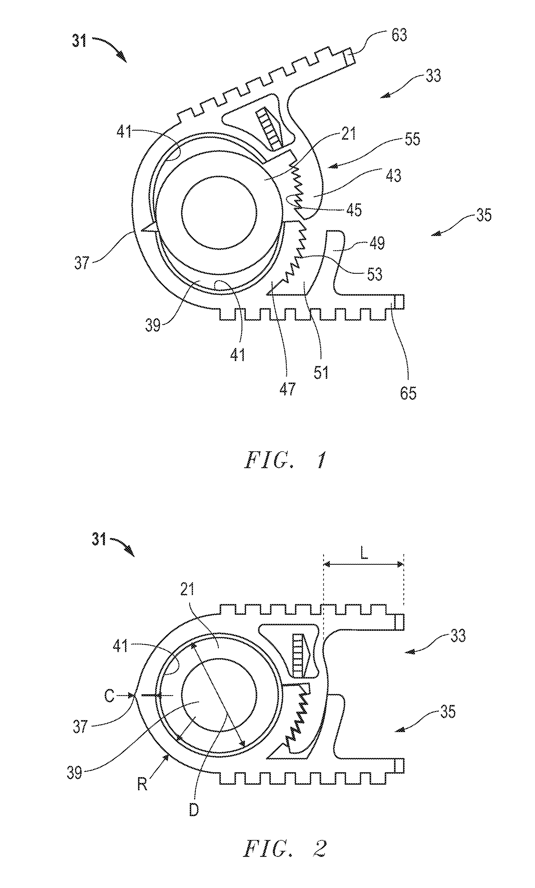
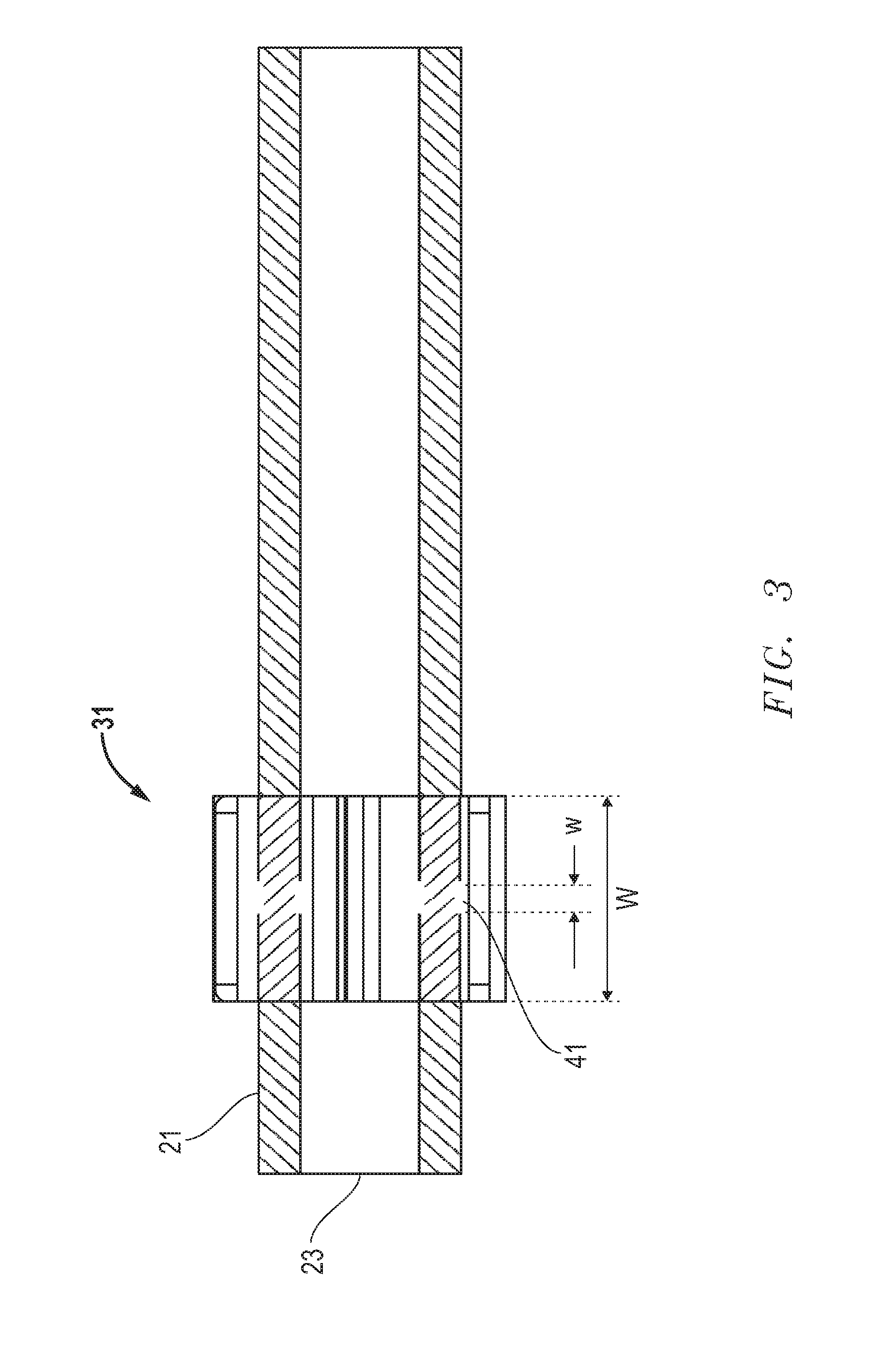
[0017]Embodiments may comprise a tubing 21 having an axial end 23 (FIG. 3). A fitting 25, such as the barbed fitting shown in FIG. 6, is inserted into the end 23 of the tubing 21. A retainer 31 is clenched (FIGS. 2 and 3) on the tubing 21 adjacent the end 23 around the fitting 25 (FIG. 6) to form a substantially 360° compression seal and connection therebetween.

[0018]In the illustrated embodiments, the retainer 31 may further comprise a body having first and second portions 33, 35 joined by one or more hinges 37 and movable from an unlocked open position (FIG. 1) to a locked closed position (FIGS. 2 and 3). The locked closed position defi...


PUM


Abstract

A retainer clenches on tubing to secure a fitting and form a compression seal and connection therebetween. The retainer has first and second portions joined by a hinge and is movable from an open position to a closed position. The closed position defines an aperture in which the tubing and fitting are clenched. The retainer has a small aspect ratio with respect to the diameter and axial width of the retainer. A rib circumscribes and extends radially into the aperture to place a pre-load on the tubing to intensify a compression force of the retainer.

Description

[0001]This application claims priority to and the benefit of U.S. Provisional App. No. 61 / 291,702, filed Dec. 31, 2009, and is incorporated herein by reference in its entirety.FIELD OF THE DISCLOSURE[0002]The invention relates in general to retainers and, in particular, to an improved system, method and apparatus for a tubing connector that creates compression between tubing and a hose-barbed fitting.BACKGROUND[0003]The connection of thermoplastic-elastomer (TPE) or silicone tubing is typically accomplished with a fitting that is inserted into the tubing and is secured with an external plastic clamp or retainer. The fittings usually comprise barbed connectors, and the retainers comprise zip ties, worm gear clamps, Kwik Clamps™, BarbLock® connectors and the like. Zip ties are inexpensive but form unreliable seals for some applications, and the other types of connectors are more expensive.[0004]In pharmaceutical and medical applications, such tubing connections are often subjected to ...

Claims


Application Information

Patent Timeline
IPC IPC(8): F16L55/00
CPCF16L33/035A61M2039/087A61M39/08
Inventor SNYDER, MITCHELL L.LESLIE, ROD J.ZOELLNER, CLEMENS E.SCHOOK, JEANDIODATI, ANTHONY M.
Owner SAINT GOBAIN PERFORMANCE PLASTICS CORP
Why Eureka
Try Eureka