Electrical machines

a technology of electric machines and converters, applied in the field of electric machines, can solve the problems of unsuitable electrical power generation, unsuitable for motor applications, and high converter volt-ampere ratings, and achieve the effect of large torqu

Active Publication Date: 2011-07-07
MAGNOMATICS LTD
View PDF13 Cites 35 Cited by
  • Summary
  • Abstract
  • Description
  • Claims
  • Application Information

AI Technical Summary

Benefits of technology

[0020]As a result of advantages of embodiments of the present invention, the invention will be better suited than the prior-art machine for machines where a large torque is r

Problems solved by technology

However, while such a high-speed electrical machine in conjunction with a mechanical gearbox allows high system torque densities to be realised, such mechanical gearboxes usually require lubrication and cooling.
Furthermore, reliability can also be a significant issue.
Some direct drive electrical machines, such as permanent magnet rotary/linear homopolar (transverse-field) machines (TFM) have poor power factors which make them unsuitable for electrical power generation and require higher converter volt-ampere ratings for motor applications.
Such designed-to-accommodate-peak-to

Method used


Image

  • Electrical machines
  • Electrical machines
  • Electrical machines

Examples


second embodiment

[0047]The shown second embodiment comprises a winding which is configured to produce a magnetic field with 2 pole-pairs. However, it will be realised that other winding configurations which generate a different number of poles may be envisaged. The current supplied to the windings by a controller may be DC or AC. When the current is AC the magnetic field moves at a different speed compared to the mechanical speed of the rotor.

[0048]The second embodiment may be used in applications where the inner rotor 202 rotates at high-speed. This results from the inner rotor 202 being more aerodynamic than the corresponding design of the first embodiment.

third embodiment

[0049]FIG. 5 shows an electrical machine 300 according to a

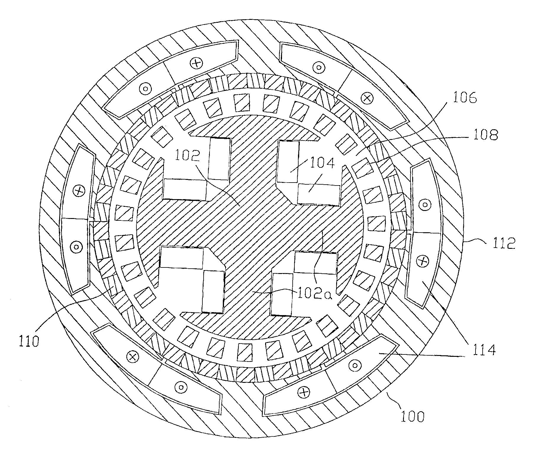
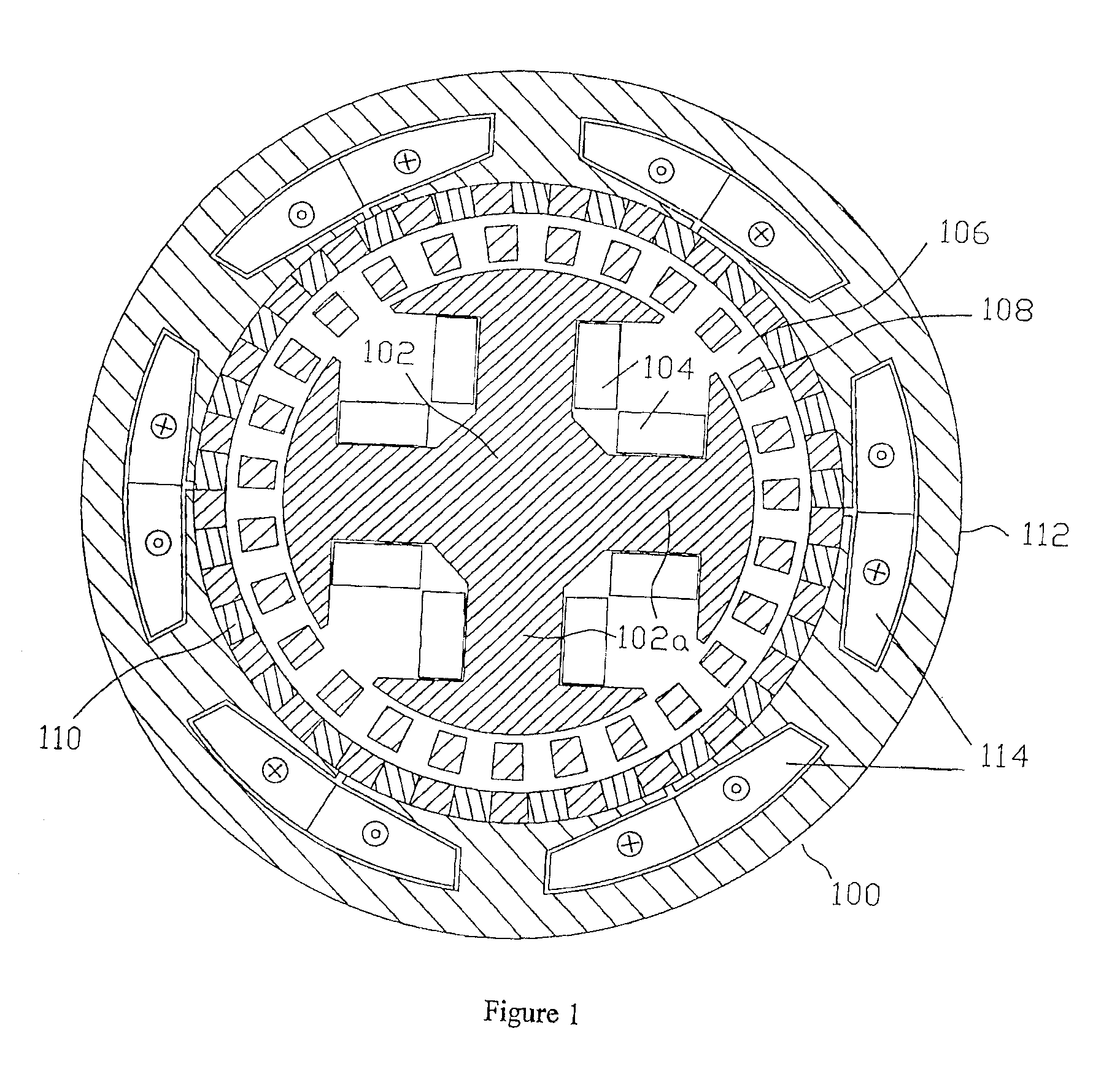
[0050]The electrical machine 300 comprises an inner rotor 302 bearing a plurality of electrical windings 304 forming electromagnets, as in the first embodiment 100. In the illustrated embodiment 300, windings forming 4 magnetic poles are illustrated but some other number of windings forming another number of poles could equally well be used.

[0051]The electrical machine 300 comprises an outer rotor 306 bearing a plurality of permanent magnets 308. In the illustrated embodiment, permanent magnets 308 having 23 pole-pairs form part of the outer rotor 306. However, the outer rotor could produce a magnetic field which has some other number of poles. The electrical machine 300 comprises a stationary armature 310 bearing a plurality of pole-pieces 312 and a 3-phase winding 314. The number of pole-pieces 312 in the embodiment is 27, although some other number of pole-pieces 312 can be used in other embodiments. It should be noted th...

sixth embodiment

[0063]The present invention also extends to embodiments as described with reference to the sixth embodiment, but in which various components take up a different position in the machine compared to the embodiment shown in FIG. 8, i.e. the inner permanent magnet array 616 becomes the most outward component, the pole-piece array 612 is positioned inwards from the permanent magnet array 616, the high-speed rotor 606 is positioned inwards from the pole-piece array 612 and the stator 602 becomes the most inward component.

[0064]As discussed above, embodiments of the present invention are particularly suited to use with turbines which generate torque at varying power levels, such as wind turbines. FIG. 9 shows a wind turbine operating with an embodiment of the present invention comprising blades 710 for being rotated by the wind, a primary gear stage 720, although it will be realised that this is not essential, an embodiment of the present invention 730 arranged as an electro-mechanic gener...


PUM


Abstract

Embodiments provide an electrical machine, comprising: first and second moveable elements arranged to interact in a magnetically geared manner via a magnetic field created, at least in part, by a first electrical winding arrangement associated with the first moveable element; and a second electrical winding arrangement which is arranged to interact magnetically with a fundamental harmonic of a magnetic field created by the first electric winding arrangement associated with the first moveable element.

Description

FIELD OF THE INVENTION[0001]The present invention relates to electrical machines.BACKGROUND TO THE INVENTION[0002]Mechanical gearboxes are extensively used to match the operating speed of prime-movers to the requirements of their loads for both increasing the rotational speed such as, for example, in wind-powered generators or reducing rotational speed such as, for example, in an electric-ship propulsion arrangement. It is usually more cost and weight effective to employ a high-speed electrical machine in conjunction with a mechanical gearbox to achieve requisite speed and torque characteristics. However, while such a high-speed electrical machine in conjunction with a mechanical gearbox allows high system torque densities to be realised, such mechanical gearboxes usually require lubrication and cooling. Furthermore, reliability can also be a significant issue. Consequently, direct drive electrical machines are employed in applications where a mechanical gearbox cannot be used. Some...

Claims


Application Information

Patent Timeline
IPC IPC(8): H02K16/02
CPCH02K7/11H02K49/102H02K7/1838Y02E10/725H02K51/00Y02E10/72
Inventor RENS, JAN JOZEFATALLAH, KAIS
Owner MAGNOMATICS LTD
Why Eureka
Try Eureka