Display input device

a technology of input device and display screen, which is applied in the field of display input device, can solve the problems of inability to provide a new user interface using the three-dimensional touch panel disclosed in patent reference 2, and impaired equipment operability, and achieve the effect of improving operability

Active Publication Date: 2011-07-07
MITSUBISHI ELECTRIC CORP
View PDF8 Cites 81 Cited by
  • Summary
  • Abstract
  • Description
  • Claims
  • Application Information

AI Technical Summary

Benefits of technology

[0010]In accordance with the present invention, the display input device can achieve a further improvement in operability.

Problems solved by technology

However, because the icon positioned in the vicinity of the position where the user's finger is close to the touch panel is simply enlarged and displayed on the screen, the user needs to move his or her finger in many directions to perform an operation on vehicle-mounted information equipment in which icons are distributedly arranged on the screen, and such a movement is not preferable for safe driving.
Furthermore, a new user interface using the three-dimensional touch panel disclosed by patent reference 2 has not been provided yet.
However, in this case, because the display position at which the icon is displayed is dependent upon the mounting position of the arm switch, and a touch of the user's hand on the arm switch is needed to change the arrangement of icons displayed on the screen, the operability of the equipment may be impaired conversely.

Method used


Image

  • Display input device
  • Display input device
  • Display input device

Examples


embodiment 1

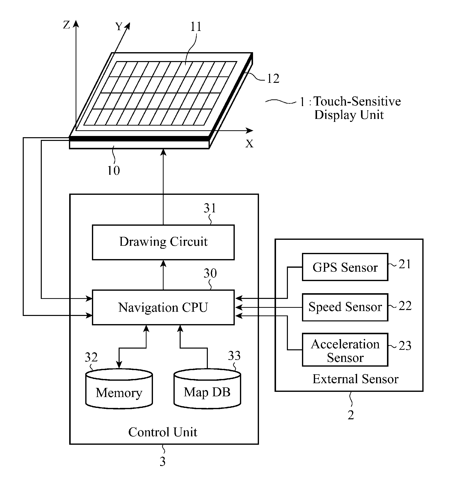
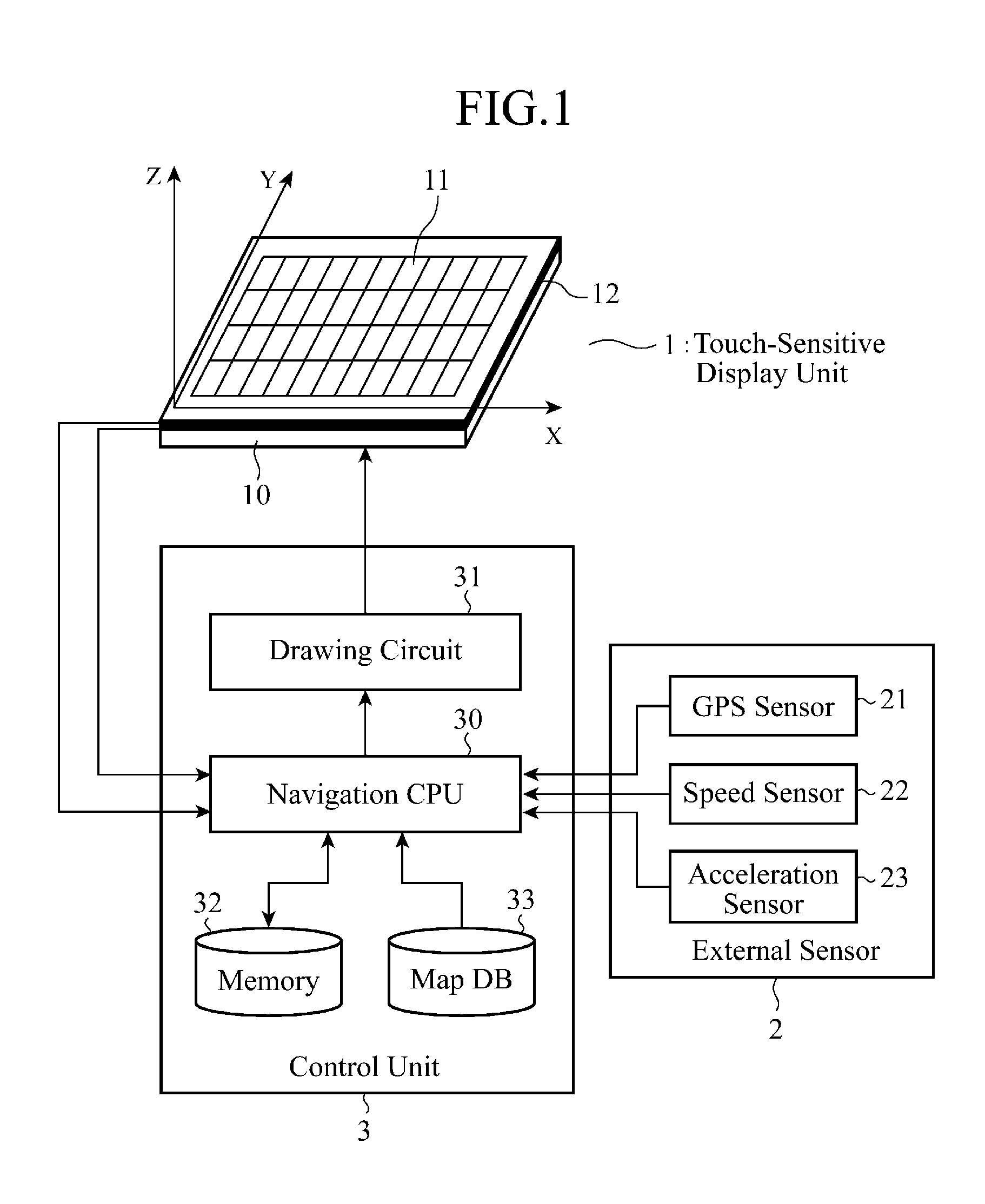
[0027]FIG. 1 is a block diagram showing the structure of a display input device in accordance with Embodiment 1 of the present invention. As shown in FIG. 1, the display input device in accordance with Embodiment 1 of the present invention is comprised of a touch-sensitive display unit (abbreviated as a touch panel from here on) 1, external sensors 2, and a control unit 3.

[0028]The touch panel 1 carries out a display of information and an input of the information. For example, the touch panel 1 is constructed in such a way that a touch sensor 11 for inputting information is laminated on an LCD panel 10 for displaying information. In this embodiment, the touch panel 1 and a plurality of proximity sensors 12 each of which carries out non-contact detection in two dimensions of a movement of an object to be detected, such as a finger or a pen, which is positioned opposite to the touch panel 1 are mounted on a peripheral portion outside the touch sensor 11.

[0029]In a case in which each o...

embodiment 2

[0076]FIG. 7 is an operation conceptual diagram showing the operation of a display input device in accordance with Embodiment 2 of the present invention on the screen of a touch panel.

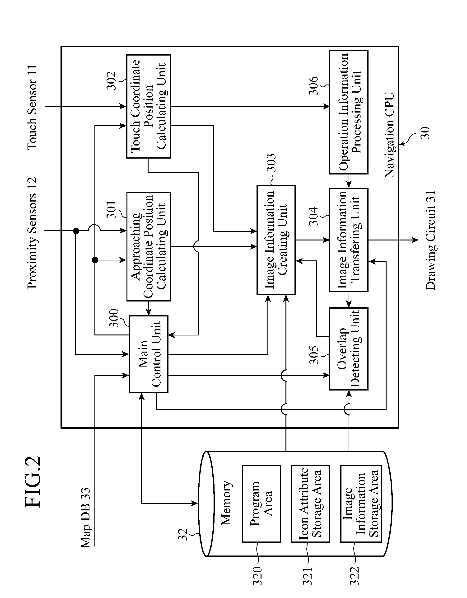
[0077]The display input device in accordance with Embodiment 2 of the present invention uses the same structure as that of the display input device shown in FIG. 1, and also uses the same program structure as that of the navigation CPU 30 shown in FIG. 2, like that of above-mentioned Embodiment 1.

[0078]The display input device in accordance with Embodiment 1 which operates according to the flow chart shown in FIG. 4 moves icons displayed on the touch panel 1 to the position shown by the XY coordinate values Oxy of a finger approaching the touch panel to display the icons at the position shown by the XY coordinate values. In contrast, the display input device in accordance with Embodiment 2, which will be explained hereafter, brings icons displayed on the touch panel 1 close to not the position shown by...

embodiment 3

[0082]FIG. 8 is an operation conceptual diagram showing the operation of a display input device in accordance with Embodiment 3 of the present invention on the screen of a touch panel.

[0083]The display input device in accordance with Embodiment 3 of the present invention uses the same structure as that of the display input device shown in FIG. 1, and also uses the same program structure as that of the navigation CPU 30 shown in FIG. 2, like that of above-mentioned Embodiment 1.

[0084]In the display input device in accordance with Embodiment 3, which will be explained hereafter, when the proximity sensors 12 detect that a finger is positioned in a left half of the touch panel 1 (when viewed from above), as shown in FIG. 8(a), a navigation CPU 30 moves an icon group close to the stop position of the finger according to a first pattern (A) in which the one or more icons according to their icon attributes are arranged to display the icon group in the vicinity of the position.

[0085]In con...


PUM


Abstract

A display input device is comprised of a touch panel 1 for carrying out a display of information and an input of information, a proximity sensor 12 for detecting a movement of an object to be detected which is positioned opposite to the touch panel 1 in a noncontact manner, and a control unit 3 for, when the proximity sensor 12 detects an approach of the object to be detected to within a predetermined distance from the touch panel 1, moving a specific display object displayed on the touch panel 1 close to a stop position of the object to be detected to display the specific display object.

Description

FIELD OF THE INVENTION[0001]The present invention relates to a display input device which is particularly suitable for use in vehicle-mounted information equipment such as a navigation system.BACKGROUND OF THE INVENTION[0002]A touch panel is an electronic part which is constructed of a matrix-shaped touch sensor laminated on an LCD (liquid crystal display) panel, for example, and is a display input device that can allow a user to touch an input button display area, such as an icon displayed on the LCD panel, by using an object to be detected, such as a finger or a pen, and detect information about the coordinate position of a part on the screen which has been touched by the user to enable the user to operate target equipment. Therefore, in many cases, a touch panel is used while being incorporated into equipment, such a vehicle-mounted navigation system or a bank ATM (Automatic Teller Machine), which has to meet the need for the user to handle the equipment by following a self-expla...

Claims


Application Information

Patent Timeline
Patent Type & Authority Applications(United States)
IPC IPC(8): G09G5/00G06F3/041G06F3/0485G06F3/0488
CPCG06F3/0416G06F3/04886G06F3/0488
Inventor SHIMOTANI, MITSUOMATSUBARA, TSUTOMUSADAHIRO, TAKASHIOHTA, MASAKOOKANO, YUICHISEMPUKU, TSUYOSHI
Owner MITSUBISHI ELECTRIC CORP
Why Eureka
Try Eureka