Camera body and imaging device

a technology for imaging devices and cameras, applied in the field of cameras and imaging devices, can solve problems such as new problems, damage to shutter units and other such parts disposed near the body mounts, and difficulty in reducing the size of camera bodies, so as to achieve high reliability, and prevent damage to shutter units 190

Active Publication Date: 2011-07-07
PANASONIC INTELLECTUAL PROPERTY MANAGEMENT CO LTD
View PDF16 Cites 100 Cited by
  • Summary
  • Abstract
  • Description
  • Claims
  • Application Information

AI Technical Summary

Benefits of technology

[0007]The technology disclosed herein allows a camera body and imaging device that are compact and highly reliable to be provided.
[0008]A camera body disclosed herein allows the mounting of a lens unit configured to form an optical image of a subject. This camera body comprises a body mount, an imaging element, a shutter unit, and a shutter controller. The body mount allows the lens unit to be mounted. The imaging element is configured to convert the optical image of the subject into an electrical signal. The shutter unit is disposed between the body mount and the imaging element and is provided so that the optical path can be blocked between the lens unit and the imaging element. The shutter controller is configured to control

Problems solved by technology

With a conventional interchangeable lens type of digital camera, however, because a mirror box apparatus is provided, it is difficult to reduce the size of the camera body.
Nevertheless, the inventors discovered that a new problem is encountered when no mirror box apparatus is installed in the camera body.
Mo

Method used


Image

  • Camera body and imaging device
  • Camera body and imaging device
  • Camera body and imaging device

Examples


first embodiment

[0023]1: Configuration

[0024]1-1: Summary of Digital Camera

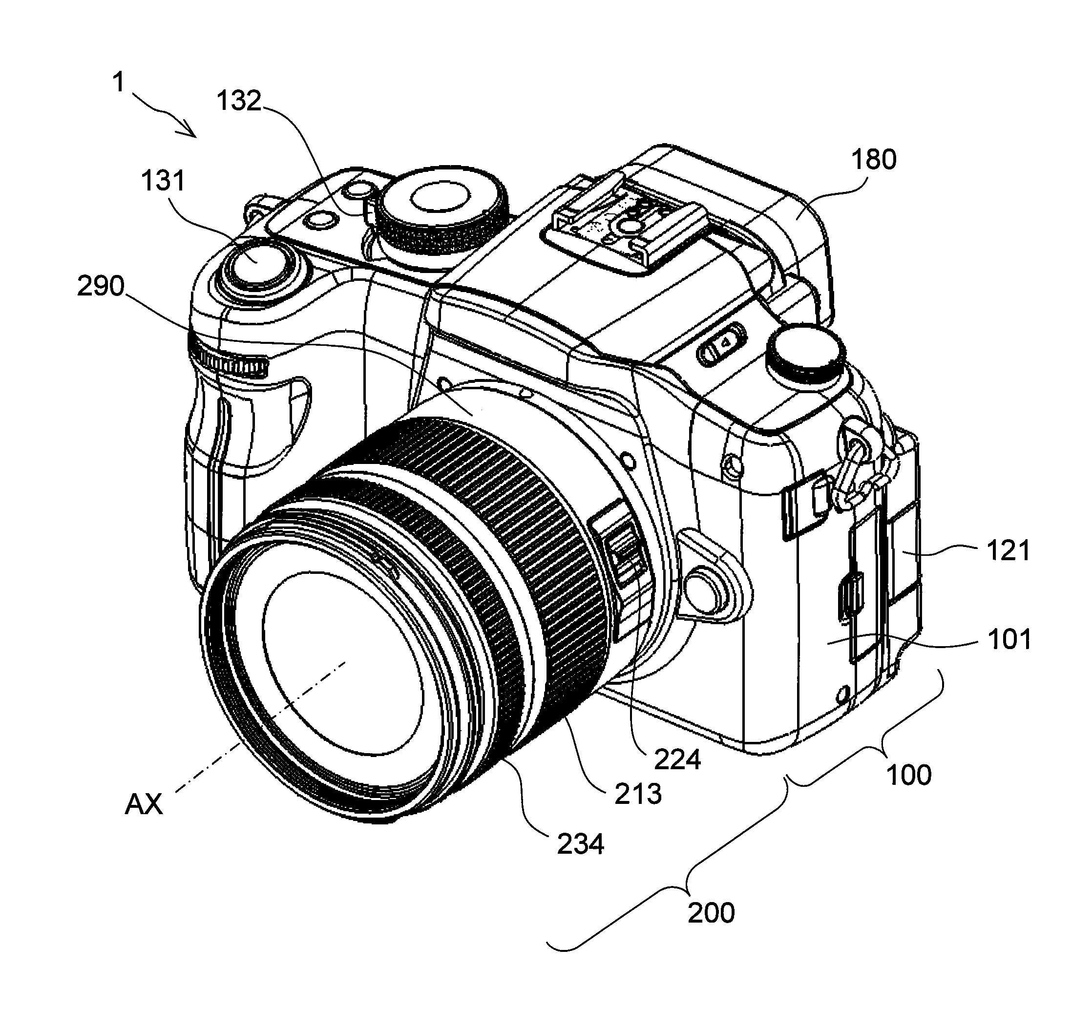
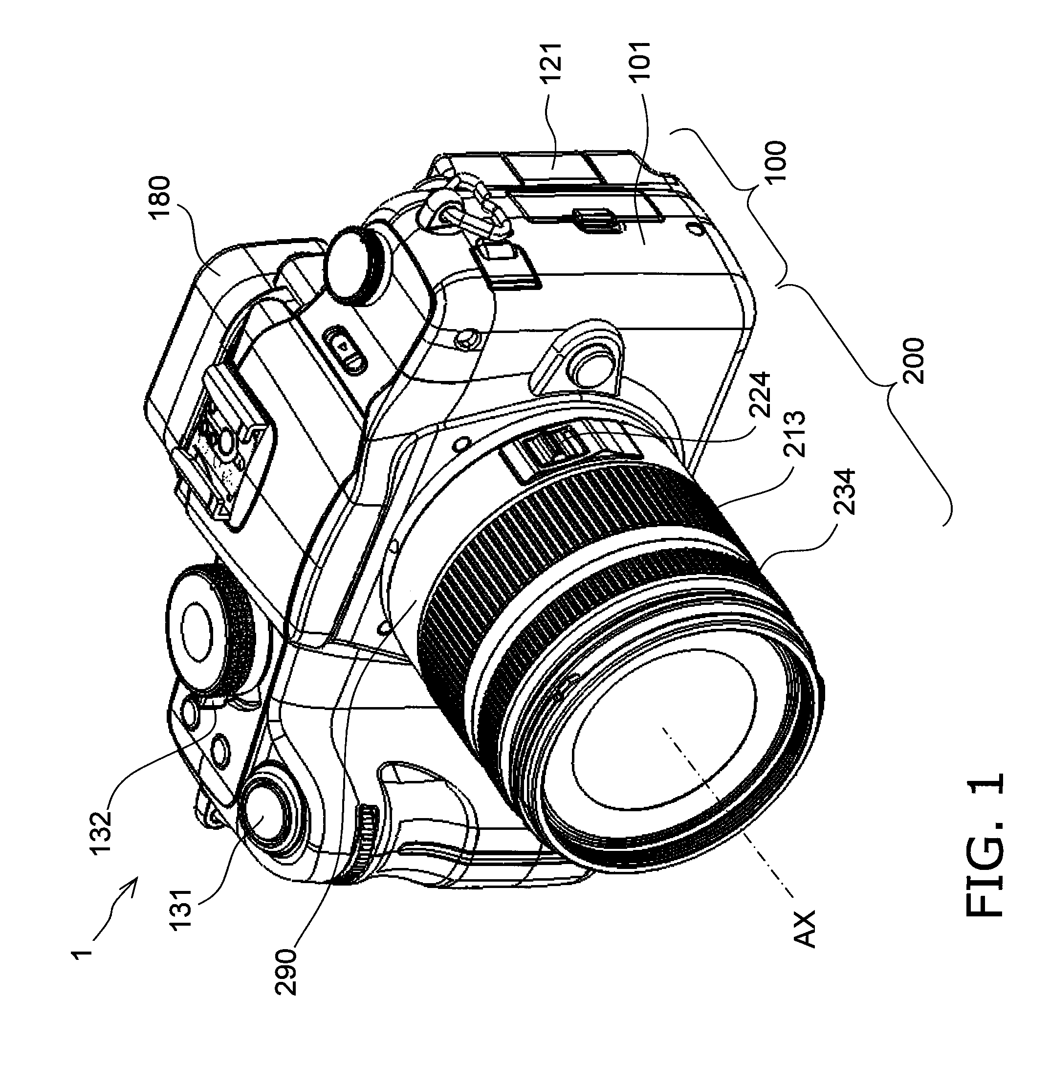
[0025]As shown in FIGS. 1 to 3, the digital camera 1 pertaining to a first embodiment comprises a camera body 100 and a lens unit 200 that can be mounted to the camera body 100.

[0026]Unlike a conventional single lens reflex camera, the camera body 100 has no mirror box apparatus, so compared to a conventional single lens reflex camera, the flange back is shorter, and making the flange back shorter allows the camera body 100 to be more compact. Furthermore, shortening the flange back affords greater latitude in designing the optical system, so the lens unit 200 can be made more compact.

[0027]For the sake of convenience in the following description, the subject side of the digital camera 1 will be referred to as “front,” the image plane side as “rear” or “back,” the vertical upper side in the normal orientation (hereinafter also referred to as landscape orientation) of the digital camera 1 as “top,” and the vertical lower side ...

second embodiment

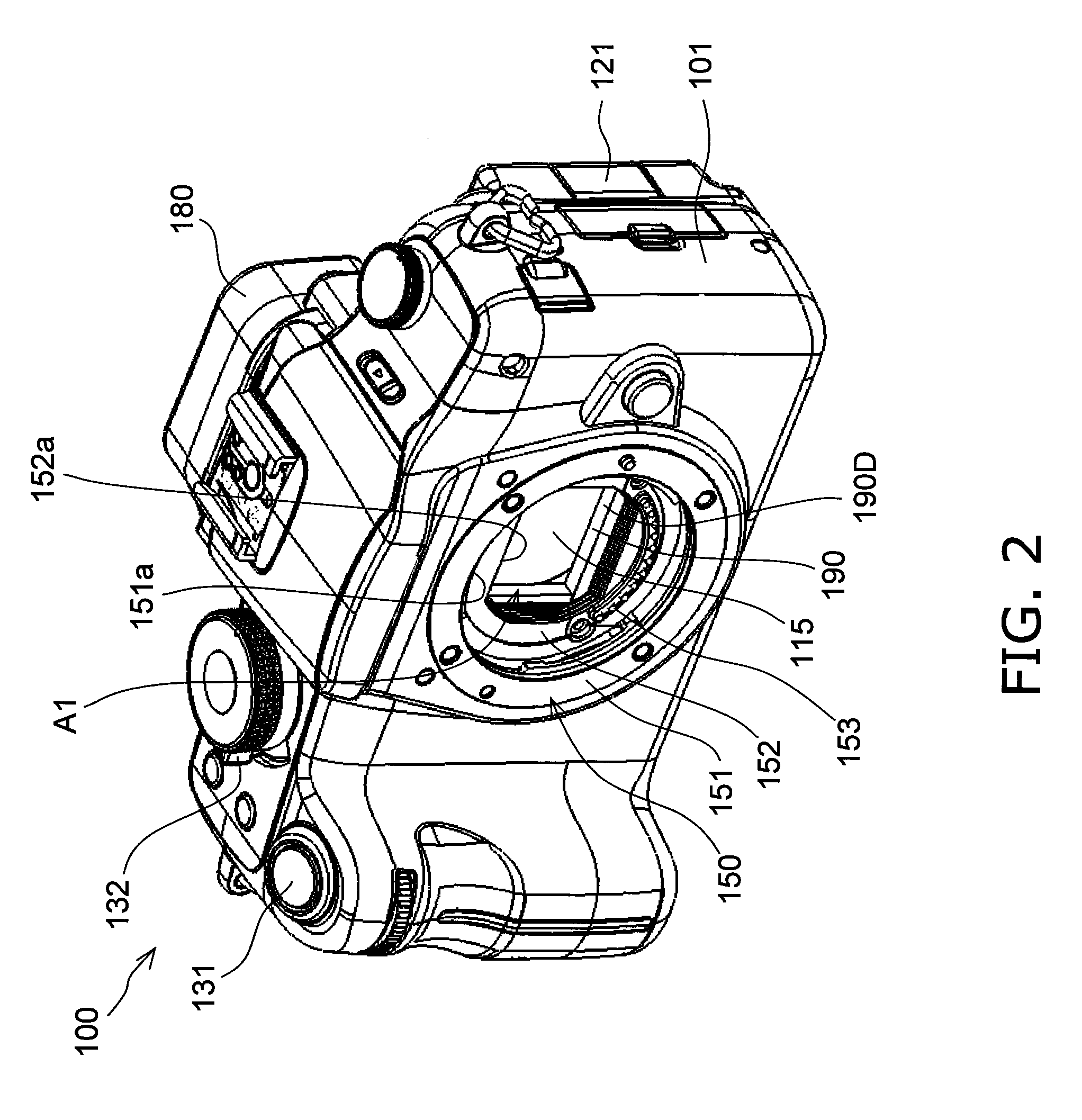
[0143]Only those differences from the camera body 100 in the first embodiment will be described here, and portions that are shared will not be described again. Furthermore, those components having substantially the same function as in the first embodiment will be numbered the same. A camera body 300 pertaining to a second embodiment will now be described. FIG. 8A is a plan view of a body mount 150 and its surroundings. FIG. 8B is a simplified configuration diagram of the camera body 300.

[0144]The camera body 100 of the first embodiment has the diaphragm 115 and an anti-condensation layer on the front face thereof, but even so, dust or other such dirt may adhere. If this happens, the user may try to remove the dirt by wiping this face with a cloth or the like.

[0145]However, it is difficult to completely wipe away the dirt. In particular, dirt tends to be pushed to the edges of the regions wiped with a cloth or the like, and this dirt tends to remain.

[0146]In view of this, with this c...


PUM


Abstract

A camera body 100 comprises a body mount 150, a CMOS image sensor 110, a shutter unit 190, and a shutter controller 145. The body mount 150 allows the lens unit 200 to be mounted. The CMOS image sensor 110 is configured to convert an optical image of a subject into an electric signal. The shutter unit 190 is disposed between the body mount 150 and the CMOS image sensor 110, and is configured to block the optical path between the lens unit 200 and the CMOS image sensor 110. The shutter controller 145 is configured to control the shutter unit 190 to maintain the shutter unit 190 in the open state in a state in which the supply of power is halted.

Description

TECHNICAL FIELD[0001]The present invention relates to a camera body which allows a lens unit to be mounted, and to an imaging device equipped with this camera body.BACKGROUND ART[0002]An interchangeable lens type of digital camera is a known imaging device (see Patent Literature 1, for example. The camera discussed in Patent Literature 1 has a lens unit and a camera body. This camera body has a CCD (charge coupled device) image sensor or other such imaging element, and a mirror box disposed between the lens unit and the imaging element. The mirror box apparatus guides light that has passed through the lens unit to either a CCD image sensor or a prism. Light guided to the prism is guided by that prism to a viewfinder.Citation ListPatent Literature[0003]Patent Literature 1: Japanese Laid-Open Patent Application 2007-127836SUMMARY OF INVENTION[0004]With a conventional interchangeable lens type of digital camera, however, because a mirror box apparatus is provided, it is difficult to re...

Claims


Application Information

Patent Timeline
IPC IPC(8): H04N5/235
CPCG03B9/36G03B17/14H04N2101/00H04N5/232H04N5/2254H04N23/55H04N23/631
Inventor SHINTANI, DAIMURAYAMA, MASATO
Owner PANASONIC INTELLECTUAL PROPERTY MANAGEMENT CO LTD
Why Eureka
Try Eureka