
Power Train For Wind Turbine

a technology for wind turbines and power trains, applied in the direction of gearing details, machines/engines, gearing, etc., can solve the problems of increasing wear and frictional forces increasing the wear and frictional force at the gear mesh, and the bearings of supporting planetary gears subject to the same amount of misalignment, so as to achieve the effect of reducing the overall system cost and maximizing the effective step-up ratio

Active Publication Date: 2011-07-07
THE TIMKEN CO
View PDF12 Cites 19 Cited by
  • Summary
  • Abstract
  • Description
  • Claims
  • Application Information

AI Technical Summary

Benefits of technology

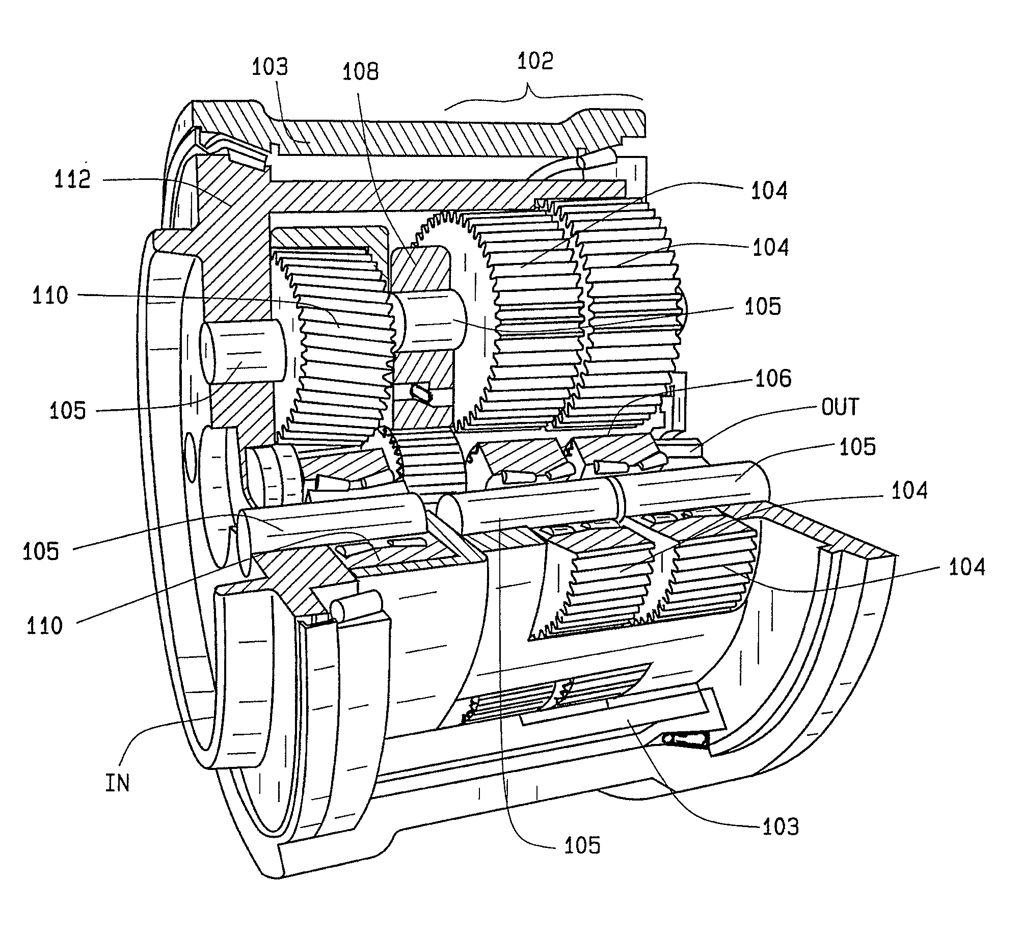
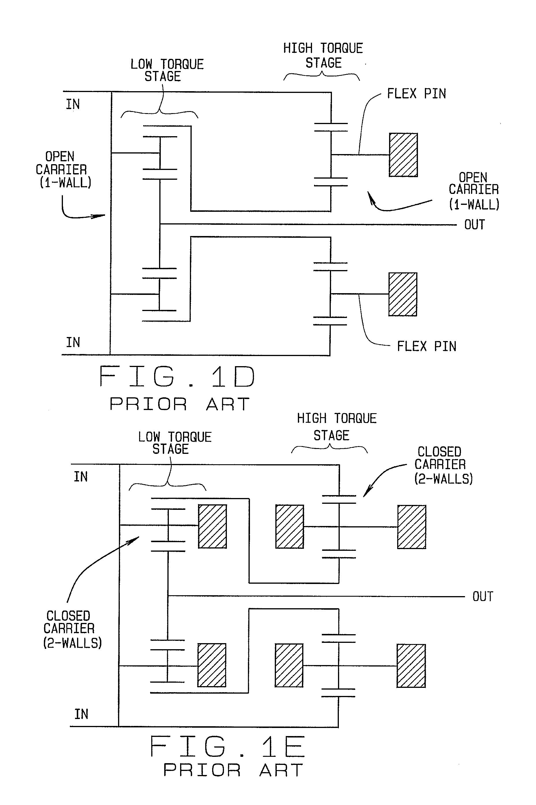
[0016]Briefly stated, the present disclosure provides a geared power train for use in a power transmission system to maximize a step-up ratio between a rotating input shaft and a rotating output shaft within a limited radial space that is defined by the planetary gearing system ring gear size. The power train is configured as a split-compound planetary gearing system with a closed-carrier flex-pin planetary gear system in a high-torque stage, and with an open-carrier flex-pin planetary gear system in a low-torque stage.

Problems solved by technology

Regardless of which gear design is used, there are two common issues which may arise.
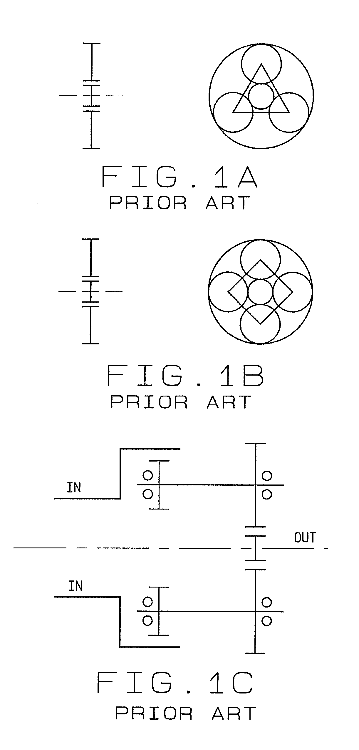
The second drawback to a conventional planetary gearing system employing a closed planetary carrier having two opposite walls connected by webbing is that the applied torsion will twist the closed planetary carrier, rotationally advancing one wall of the planetary carrier carrying one end of the planetary pins ahead of the opposite wall of the planetary carrier carrying the opposite ends of the planetary pins.
This rotational advancement misaligns the planetary gears with their mating sun gear and ring gear, resulting in increased wear and frictional forces at the gear meshes.
In addition, the supporting planetary gear bearings are subjected to the same amount of misalignment.

Method used


Image

  • Power Train For Wind Turbine
  • Power Train For Wind Turbine
  • Power Train For Wind Turbine

Examples


Embodiment Construction

[0030]The following detailed description illustrates the invention by way of example and not by way of limitation. The description enables one skilled in the art to make and use the present disclosure, and describes several embodiments, adaptations, variations, alternatives, and uses of the present disclosure, including what is presently believed to be the best mode of carrying out the present disclosure.

[0031]A power train 100 of the present disclosure is described below primarily in connection with the illustrations shown in FIGS. 2 and 3. The power train 100 is a spit-compound planetary gearing system utilizing a closed-carrier flex-pin system in a high-torque stage (Stage 1), and an open-carrier flex-pin system in a low-torque stage (Stage 2) to achieve a selected step-up ratio between the input shaft (IN) and the output shaft (OUT).

[0032]The high-torque stage (Stage 1) incorporates two adjacent arrays 102 of large-diameter planet gears 104 mounted to flex-pins 105 and driven by...


PUM


Abstract

A geared power train (100) for use in a wind turbine application to maximize a step-up ratio within a radial space that is defined by the planetary gearing system ring gear size. The geared power train (100) is configured as a split-compound planetary gearing system with a closed-carrier flex-pin planetary system in a high-torque stage (Stage 1) for receiving driving torque via an input shaft (IN) from a wind turbine, and an open-carrier flex-pin planetary system in a low-torque stage (Stage 2) coupled to the high-torque stage (Stage 1) for delivering the driving torque to an electrical generator via an output shaft (OUT).

Description

CROSS-REFERENCE TO RELATED APPLICATIONS[0001]The present application is related to, and claims priority from, U.S. Provisional Patent Application Ser. No. 61 / 095,816 filed on Sep. 10, 2008, and which is herein incorporated by reference.STATEMENT REGARDING FEDERALLY SPONSORED RESEARCH[0002]Not Applicable.BACKGROUND OF THE INVENTION[0003]The present invention is related generally to power train systems, such as those utilized in wind turbines, and specifically to an improved wind turbine power train system configured with a compound split planetary gearing system incorporating a closed carrier flex pin system in a high torque stage together with an open carrier flex pin system in a low torque stage.[0004]Wind turbine system architectures current in development are aimed at producing lean (low mass, low cost) and reliable machines. One solution being pursued is a hybrid wind turbine which incorporates a combination of a simplified power train (commonly a single-stage planetary gearing ...

Claims


Application Information

Patent Timeline
IPC IPC(8): F16H1/28
CPCF03D11/02F05B2240/40F05B2260/40311Y02E10/722F16H37/0833F16H57/082F16H1/2836F03D15/00F03D15/10F03D9/25Y02E10/72
Inventor FOX, GERALD P.
Owner THE TIMKEN CO
Learn More