

Machine tool device
a technology of machine tools and tools, applied in the direction of manufacturing tools, instruments, image enhancement, etc., can solve the problems of user hazard and user hazard, and achieve the effect of high monitoring reliability
- Summary
- Abstract
- Description
- Claims
- Application Information
AI Technical Summary
Benefits of technology
Problems solved by technology
Method used
Image

Examples
Embodiment Construction
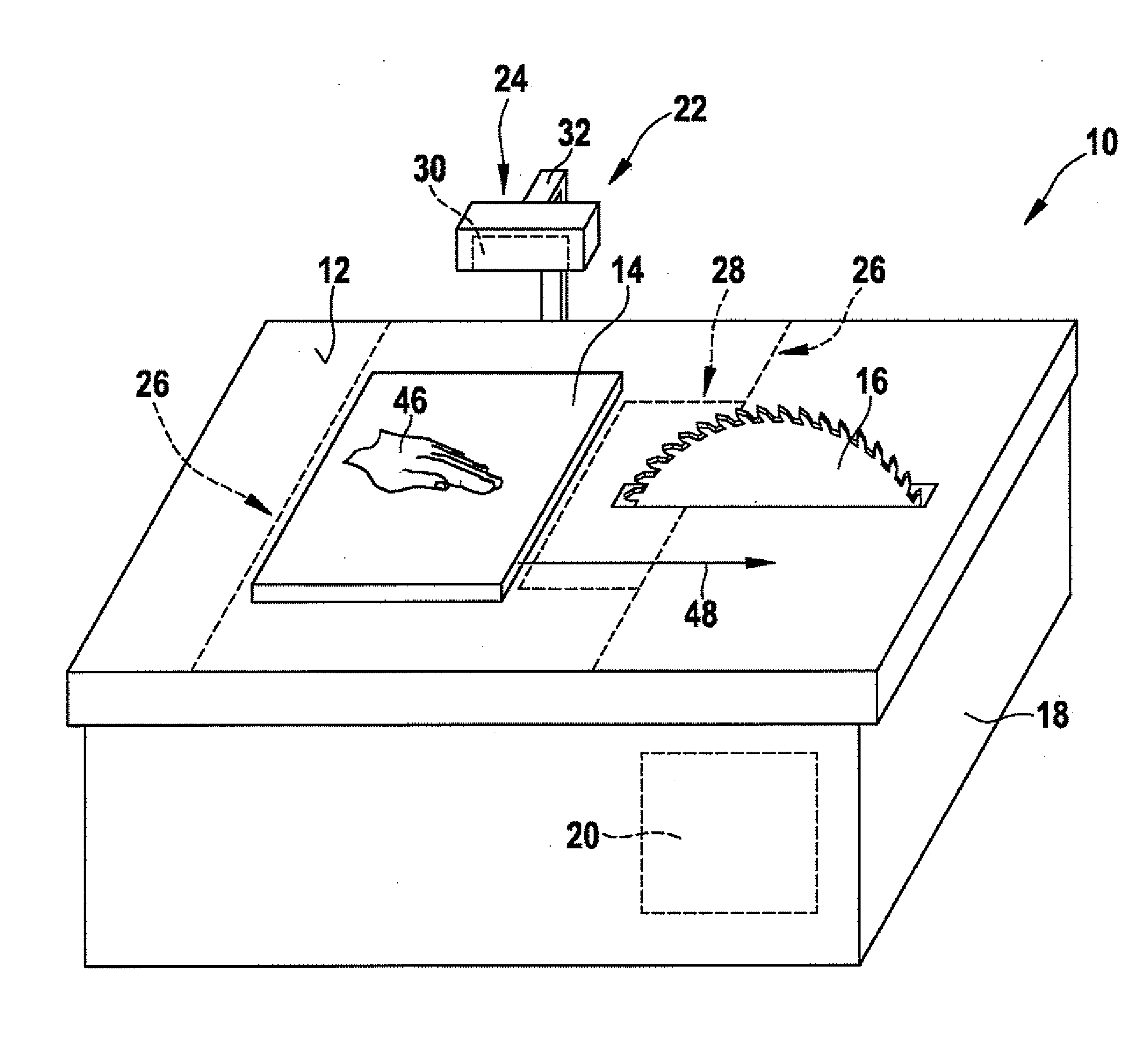
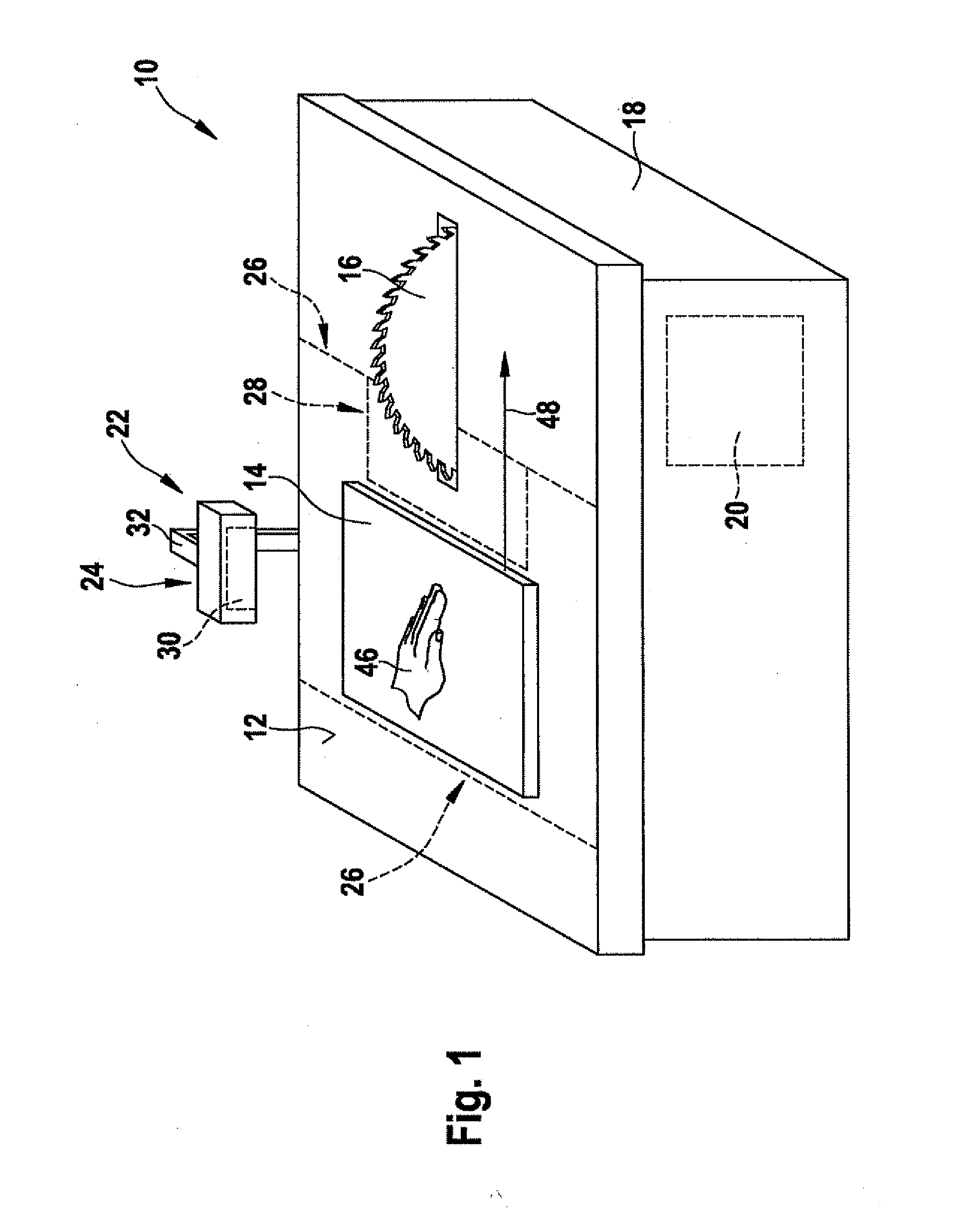
[0026]FIG. 1 shows a machine tool 10 designed as a circular table saw, in a perspective view. The machine tool has a work surface 12 which is designed as a workpiece support surface for laying a workpiece 14 to be machined, and which is horizontally oriented in a base mounting position of machine tool 10. A tool 16 designed as a circular saw blade projects from work surface 12. In a workpiece machining operation, tool 16 is set in rotation by a drive unit 20 which is located in a drive housing 18 situated beneath work surface 12 and which is designed as an electric motor.
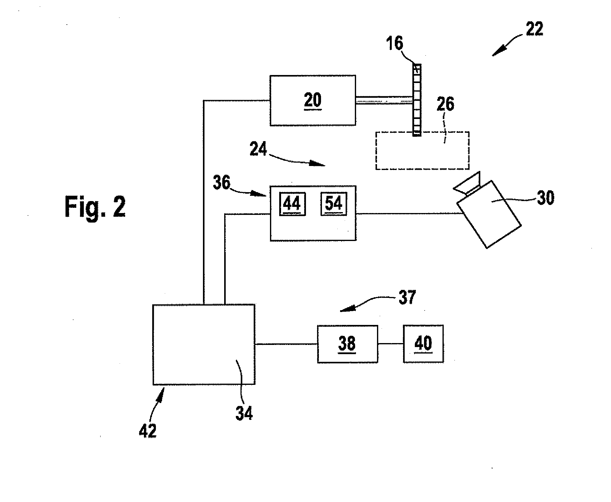
[0027]Machine tool 10 includes a machine tool device 22 having a monitoring unit 24. This monitoring unit 24 is provided for monitoring a machine tool monitoring range 26. The boundary of machine tool monitoring range 26 on work surface 12 is schematically illustrated by dashed lines in FIG. 1. Machine tool monitoring range 26 contains a partial range of work surface 12, and also extends vertically upward starting f...
PUM
| Property | Measurement | Unit |
|---|---|---|
| velocity | aaaaa | aaaaa |
| optical data | aaaaa | aaaaa |
| optical flow method | aaaaa | aaaaa |
Abstract
Description
Claims
Application Information