
Appliance comprising polyurethane foam

a technology of polyurethane foam and polyurethane, applied in the field of applications, can solve the problems of increased energy consumption, high noise and vibration, and high noise and vibration of applications, and achieve the effect of reducing the amount of energy needed to operate and reducing the noise and vibration produced

Inactive Publication Date: 2011-07-14
BASF AG
View PDF18 Cites 46 Cited by
  • Summary
  • Abstract
  • Description
  • Claims
  • Application Information

AI Technical Summary

Benefits of technology

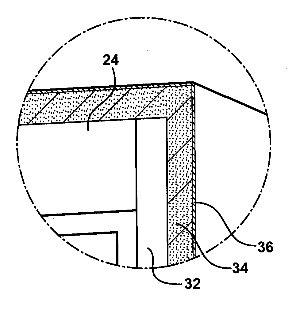
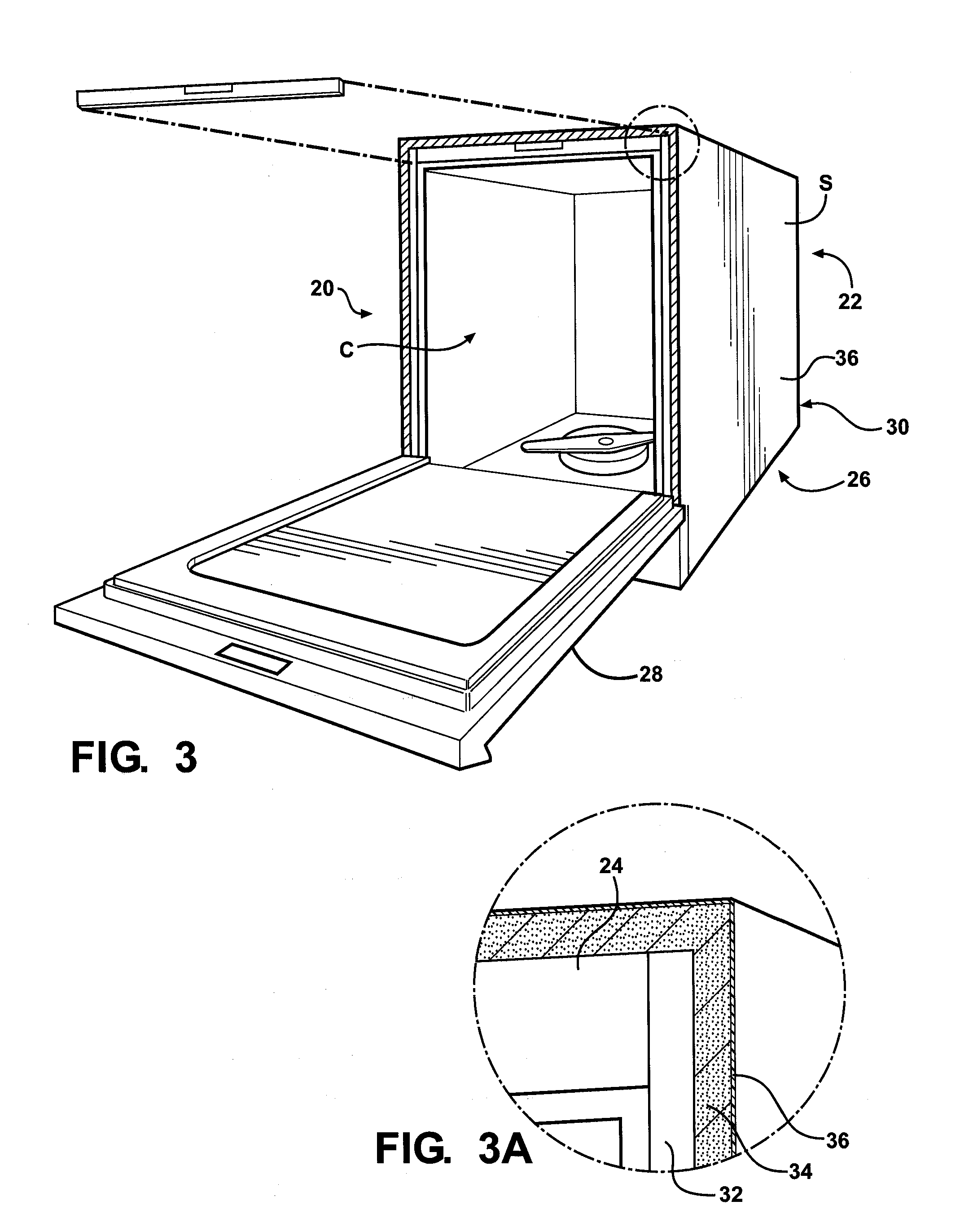
The invention is an appliance with a polyurethane foam covering that reduces noise and vibrations while also being energy efficient. The foam is applied to the outermost surface of the appliance and has specific properties that make it effective at reducing noise and vibrations. The use of the foam does not increase energy consumption or cost of use. The method for forming the appliance includes steps of applying the foam to the top panel, bottom panel, or plurality of walls. The foam is effective in reducing noise and vibrations while also reducing the amount of energy needed to operate the appliance.

Problems solved by technology

When used, these appliances tend to produce high levels of noise and vibration which reverberate in the metals and are commercial undesirable.
In dishwashers, the noise and vibration typically originate from water spray, from water pumps, and from various internal mechanisms.
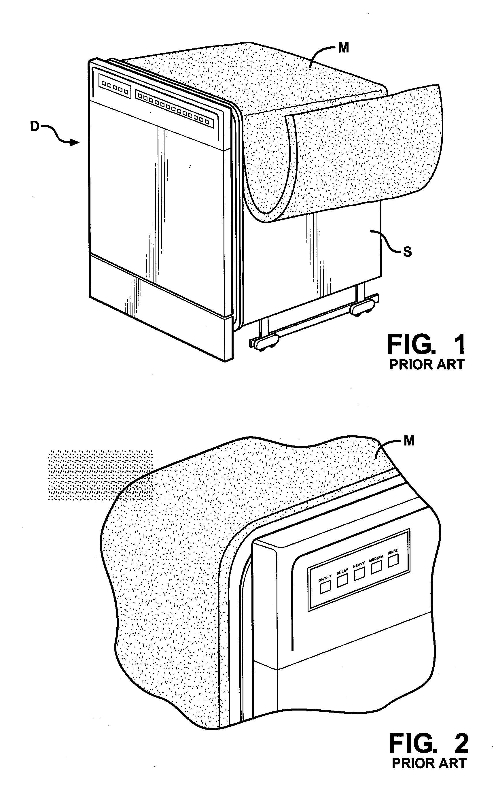
However, these coverings significantly increase the thermal mass of the appliance which results in greater energy consumption and higher cost of use.
Since the appliance and the asphalt mastic covering have a combined high thermal mass, long heating times and large amounts of energy are required.
This not only increases energy usage but also increases costs, both of which are commercially undesirable.
Current federal standards, along with proposed 2012 Federal Energy Star requirements, greatly limit amounts of energy that typical appliances can consume.

Method used


Image

  • Appliance comprising polyurethane foam
  • Appliance comprising polyurethane foam
  • Appliance comprising polyurethane foam

Examples


examples

[0071]Three polyurethane foams (Foams 1-3) are formed according to the instant invention. A comparative asphalt mastic (Mastic 1) is also prepared along with a comparative foam (Comparative Foam 1). The Foams 1-3 and the Comparative Foam 1 are formulated according to the formulas set forth in Table 1 below wherein all parts are in grams unless otherwise noted. More specifically, the Foams 1-3 each include the reaction product of a resin composition and an isocyanate composition. After formation, the Foams 1-3, the Comparative Foam 1, and the Mastic 1 are evaluated to determine a variety of physical properties.

TABLE 1Compar-ativeFoam 1Foam 2Foam 3Foam 1Mastic 1ResinCompositionPolyol 146————Polyol 2—56———Polyol 35030———Polyol 4——30.2330.23—Polyol 5——2525—Polyol 6——66—Chain Extender 1—10———Catalyst 12222—Catalyst 21133—Catalyst 32222—Catalyst 40.20.20.20.2—Surfactant 10.50.50.50.5—Surfactant 2——1010—Flame Retardant——66—Plasticizer——55—Water0.070.070.070.07—Total101.7101.790.090.0—Isocy...


PUM

PropertyMeasurementUnit
densityaaaaaaaaaa
temperatureaaaaaaaaaa
glass transition temperatureaaaaaaaaaa

Abstract

An appliance includes a housing having top and bottom panels disposed opposite each other and a plurality of walls connected to the top and bottom panels. The top and bottom panels and the plurality of walls define a cavity of the appliance. The housing also has an outermost surface about which a polyurethane foam is disposed. The polyurethane foam reduces noise and vibrations emitted from the appliance during use and has a density of from 20 to 50 pounds per cubic foot (pcf). The polyurethane foam also has a damping factor of at least 0.2 measured at a temperature of from 40° C. to 60° C. Furthermore, the polyurethane foam has a k-factor of less than 2.0 btu-in / hr-ft2-° F. which reduces an amount of energy required to operate the appliance. The appliance is formed by applying the polyurethane foam to at least one of the top panel, bottom panel, and plurality of walls.

Description

FIELD OF THE INVENTION[0001]The subject invention generally relates to an appliance and a method of forming the appliance. The appliance includes a polyurethane foam that has specific damping and thermal properties and reduces noise, vibration, and energy consumption of the appliance.DESCRIPTION OF THE RELATED ART[0002]Appliances such as dishwashers, washing machines, and clothes dryers are typically fabricated from stainless steel in combination with other metals and plastics. When used, these appliances tend to produce high levels of noise and vibration which reverberate in the metals and are commercial undesirable. In dishwashers, the noise and vibration typically originate from water spray, from water pumps, and from various internal mechanisms.[0003]Efforts have been made to minimize these noises and vibrations. Typically, asphalt mastic coverings and / or fiberglass coverings are adhered to external surfaces of the appliances to reduce noise and absorb vibrations. However, these...

Claims


Application Information

Patent Timeline
Patent Type & Authority Applications(United States)
IPC IPC(8): B32B3/26B23P11/00B08B3/00
CPCA47L15/4255Y10T29/49826C08G18/3206C08G18/4816C08G18/482C08G18/6685C08G18/797C08G2101/0066C08G2101/0083C08G2105/02C08G2350/00D06F39/12G10K11/162C08G18/10Y10T428/1376C08G18/6674A47L15/4209C08G2110/0066C08G2115/02C08G2110/0083A47L15/42C08J9/00
Inventor NEFF, RAYMOND A.CARMONA, LUCYANNEPHELPS, DAVID R.
Owner BASF AG
Learn More