Vent valve assemblies for baby bottles

a technology for venting valves and bottles, applied in the direction of sealing, functional valve types, drinking vessels, etc., can solve the problems of gas and colic, infants cannot feed from bottles, and materials are very expensive, so as to reduce the pressure of sucking, relieve the vacuum, and reduce the sucking

Active Publication Date: 2011-07-14
JMBH HLDG LLC
View PDF16 Cites 19 Cited by
  • Summary
  • Abstract
  • Description
  • Claims
  • Application Information

AI Technical Summary

Benefits of technology

[0008]The present disclosure also provides an improved vent valve and vent valve assembly that alleviates the vacuum created in a liquid dispensing container, for example, an infant feeding bottle, during feeding.
[0016]The present disclosure further provides an aforementioned vent valve assembly that is easy to clean.

Problems solved by technology

The swallowed air can cause gas and colic.
Since baby bottles employing bottom venting systems may contain about five to about six inches of liquid, the need of the infant to apply a sucking pressure to activate a slit venting system could be perceived as a problem in connection with placing a strain on infants having sensitive, developing or infected ears.
Occasionally, the slits heal enough that they cannot open at all, and the infant cannot feed from the bottle.
While silicone generally is a suitable material, for example in that slits formed in silicone flexible members do not begin to open due to dishwashing and boiling heat, the material is very expensive.

Method used


Image

  • Vent valve assemblies for baby bottles
  • Vent valve assemblies for baby bottles
  • Vent valve assemblies for baby bottles

Examples


first embodiment

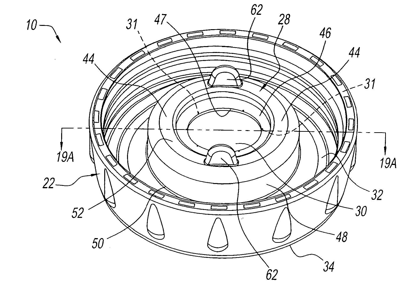
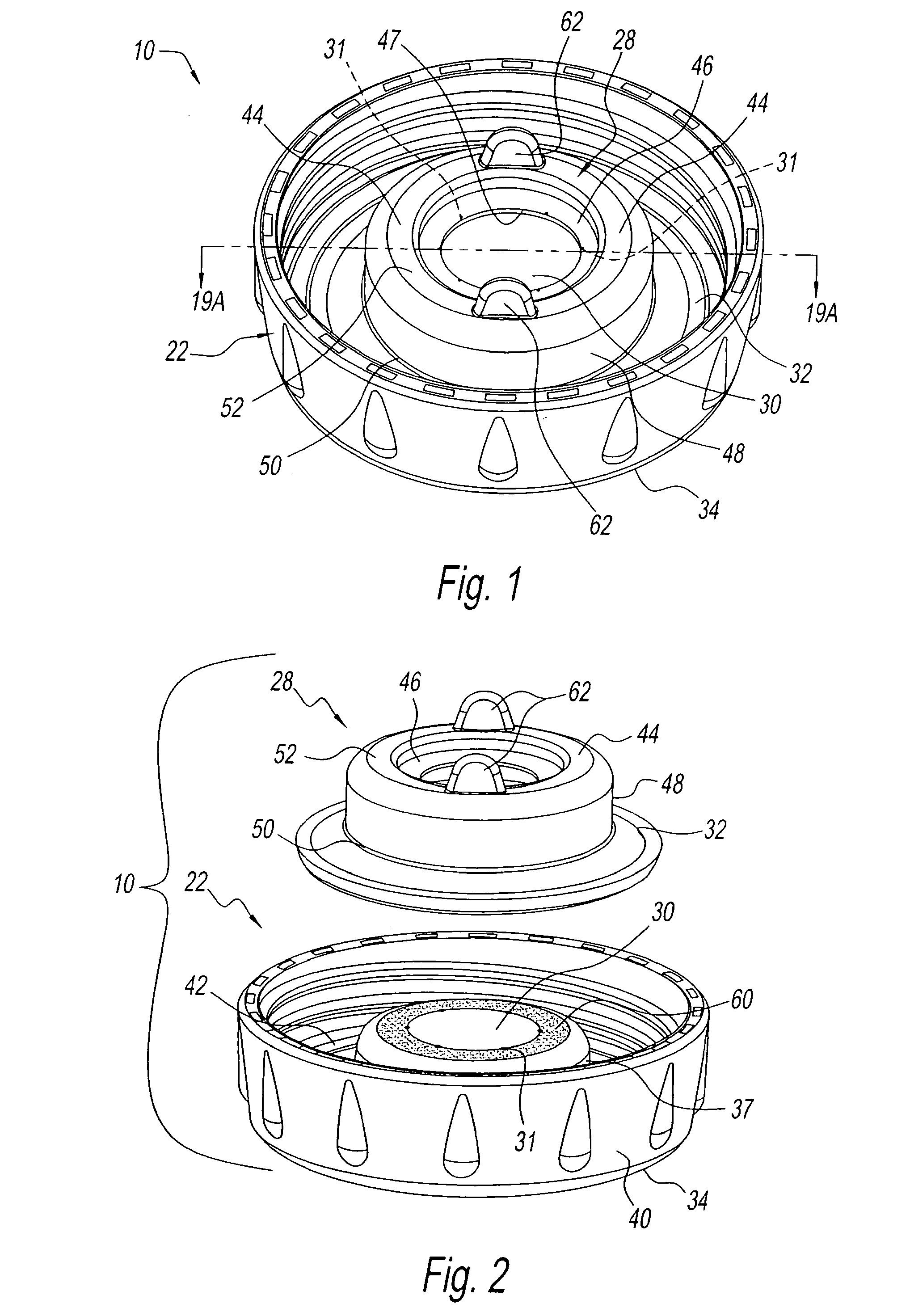
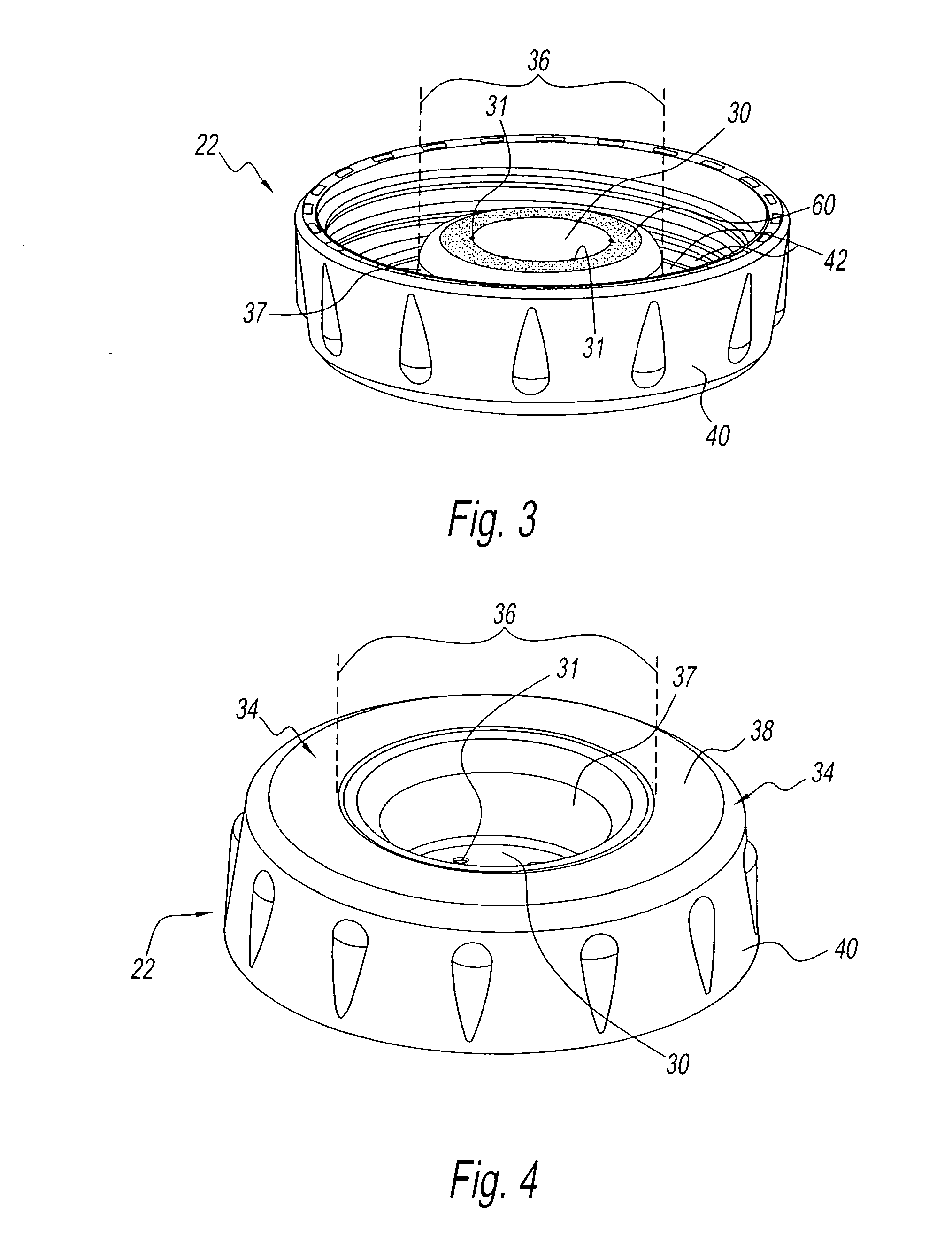
[0092]FIGS. 17 and 18 are vertical sectional views as would be seen respectively along line 17-17, and line 18-18, of FIG. 15. FIGS. 16 and 17 each show the features of the inside surface of upstanding member 48 that were shown in plan view and discussed in connection with FIG. 15. It is to be noted, however, that with respect to the preferred first embodiment of the invention, some, most, many or all of those inside surface features can be eliminated, so long as vent valve 28 is easily mountable on and removable from central portion 36, and, when it is mounted thereon, or otherwise cooperatively related with the vent disc in accordance with this disclosure, their respective vertical axes are fairly colinear, or the respective components of the vent valve assembly 10 of the invention (vent disc 30 and vent valve 28) are concentrically or otherwise cooperatively aligned, so that flap 46, or multiple flaps, however designed, cover(s) and operate(s) as intended with respect to vent hol...

second embodiment

[0105]Vent valve 128 of the present disclosure is basically the same as, and operates basically the same as vent valve 28 described earlier in connection with the first preferred embodiment of the invention. Thus, vent valve 128 shown in and described in connection with FIGS. 21, 22, 31 through 40 and 46 is basically the same and operates basically the same as vent valve 28 shown in and described in connection with FIGS. 2, 12, 13 through 19, 19A and 20. One minor difference between vent valve 128 and vent valve 28, is that vent valve 128 is presented without grasping tabs 62. Another difference is in the manner in which vent valve 128 relates to and cooperates with vent disc 130′. Whereas top portion 44 of vent valve 28 sits on a vent disc 30 that preferably is an integral portion of or is mounted on raised central portion 36 of bottom wall 34, in the second preferred embodiment of vent valve assembly 100′, vent disc 130′ is an individual or separate member that is mounted to upsta...

third embodiment

[0114]FIGS. 46 through 51 show a vent valve assembly 100″ of the present disclosure, the vent valve assembly having a further modified vent disc. FIG. 46 shows vent valve assembly 100″ is comprised of bottom cap 122′, vent valve 128, and vent disc 130′″. Vent disc 130′″ is reversible. Each of its upper and lower surfaces is a mirror image of the other. More particularly, as shown in FIGS. 46, 47, 49 and 50, which show upper surface US, (and as shown in FIG. 48 which shows lower surface LS,) each surface of disc 130″ has a first radially annular peripheral outer rim or edge 192 having a rounded edge, for being press fit into groove 190, a next or second radially inward annular peripheral portion or area 193 that is textured, and within which is positioned vent holes 131″, and a next radially inward central portion 194, within which is situated a diametrically disposed, semi-circular grasping tab 195. Since vent holes 131″ are cylindrical, there will not be any variation in vent flow ...


PUM


Abstract

A vent valve, and a vent valve assembly, for a liquid dispensing container, employ a vent disc having small open vent holes in cooperation with an overlying thin flexible flap that covers and closes the vent holes to limit liquid pressure on the holes when the container is upright, yet require little suction pressure to move the flap to draw liquid or vent through the holes. The vent valve can be used in a bottom cap that is attachable to the bottom open end of the container. The vent valve assembly includes such a bottom cap, a sealing member for sealing the bottom cap to the container, and a vent valve. The vent valve and / or bottom cap have an elevated vent disc and a top portion having the thin flexible flap.

Description

CROSS REFERENCE TO RELATED APPLICATION[0001]This application is a divisional application of U.S. application Ser. No. 12 / 004,129, filed on Dec. 20, 2007, now pending, which is based on and claims the priority and benefits of U.S. Provisional Application Ser. No. 60 / 875,899, filed Dec. 20, 2006, now abandoned, the contents of all of which are incorporated by reference herein.BACKGROUND OF THE INVENTION[0002]1. Field of the Invention[0003]The present invention relates to liquid dispensing containers that require venting, including drinking and feeding containers, for example, infant feeding bottles and cups. More particularly, the present invention relates to vent systems, including vent valves, vents and the like that are located at the bottom of such containers, to alleviate vacuum created in the containers during feeding. The present invention also relates to such vent systems that also prevent liquid from leaking from the containers.[0004]2. Description of Related Art[0005]Baby li...

Claims


Application Information

Patent Timeline
Patent Type & Authority Applications(United States)
IPC IPC(8): B65D51/16
CPCA61J9/04Y10T137/7897B65D51/16B65D53/00F16K17/18
Inventor RENZ, CHARLES J.
Owner JMBH HLDG LLC
Why Eureka
Try Eureka