Circuit structure of light-emitting diode (LED) lamp

a technology of led lamps and circuit structures, which is applied in the direction of cathode-ray/electron beam tube circuit elements, semiconductor devices for light sources, lighting and heating apparatus, etc., can solve the problems of high cost inconvenient use at ordinary homes, and high cost of the whole assembly of led lamps formed in this arrangement. achieve the effect of enhancing overall function, reducing total power consumption, and convenient us

Inactive Publication Date: 2011-07-14
CHEN HUI SAN +1
View PDF5 Cites 30 Cited by
  • Summary
  • Abstract
  • Description
  • Claims
  • Application Information

AI Technical Summary

Benefits of technology

[0007]Accordingly, the primary objective of the present invention is to provide a circuit structure of LED lamp, which comprises a combination of at least one LED lamp assembly, a current-limit resistor, a bridge rectifier, a capacitor set, a circuit board, and an electrical connector, whereby either one or more burned-out LEDs does not cause power-off of the other LEDs to conduct the power continuously through by-pass resistors so as to avoid terminating the lighting function of the other LEDs and thus to provide advantages of convenient use and significantly enhance the overall function.
[0008]The secondary objective of the present invention is to provide a circuit structure of LED lamp, which comprises a combination of at least one LED lamp assembly, a current-limit resistor, a bridge rectifier, a capacitor set, a circuit board, and an electrical connector, so as to allow direct use of household or industrial power of alternate current (AC) 100-380V, wherein the AC power, which is first rectified by the bridge rectifier and further subjected to the voltage regulated by the capacitor set, is supplied to the at least one LED lamp assembly to energize each of a number of LEDs that are connected in series without being first fed through a low-voltage transformer, and only at a minor expense of current consumed through the by-pass resistors, whereby the lighting performance of the at least one LED lamp assembly is improved and the overall operation of lighting is significantly enhanced.
[0009]In order to achieve the a

Problems solved by technology

Besides, the power supply cannot be realized through a serial connection of high voltage, so that only a limit number of LEDs can be connected in series first and then a parallel connection is made among those strings of above-mentioned serially-connected LEDs.
The whole assembly of LED lamp formed in this arrangement is of high cost, making it not conveniently to be widel

Method used


Image

  • Circuit structure of light-emitting diode (LED) lamp
  • Circuit structure of light-emitting diode (LED) lamp
  • Circuit structure of light-emitting diode (LED) lamp

Examples


Embodiment Construction

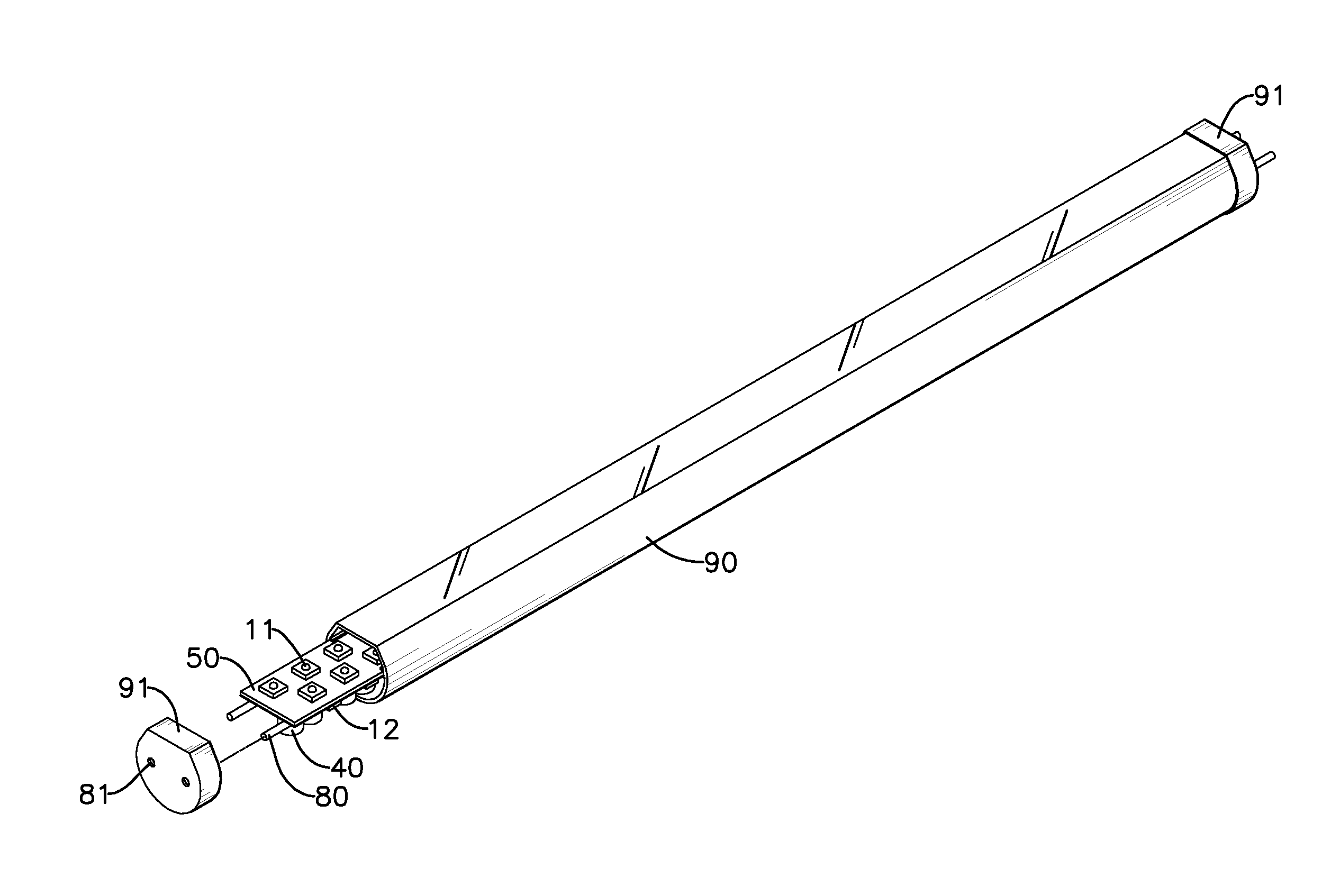
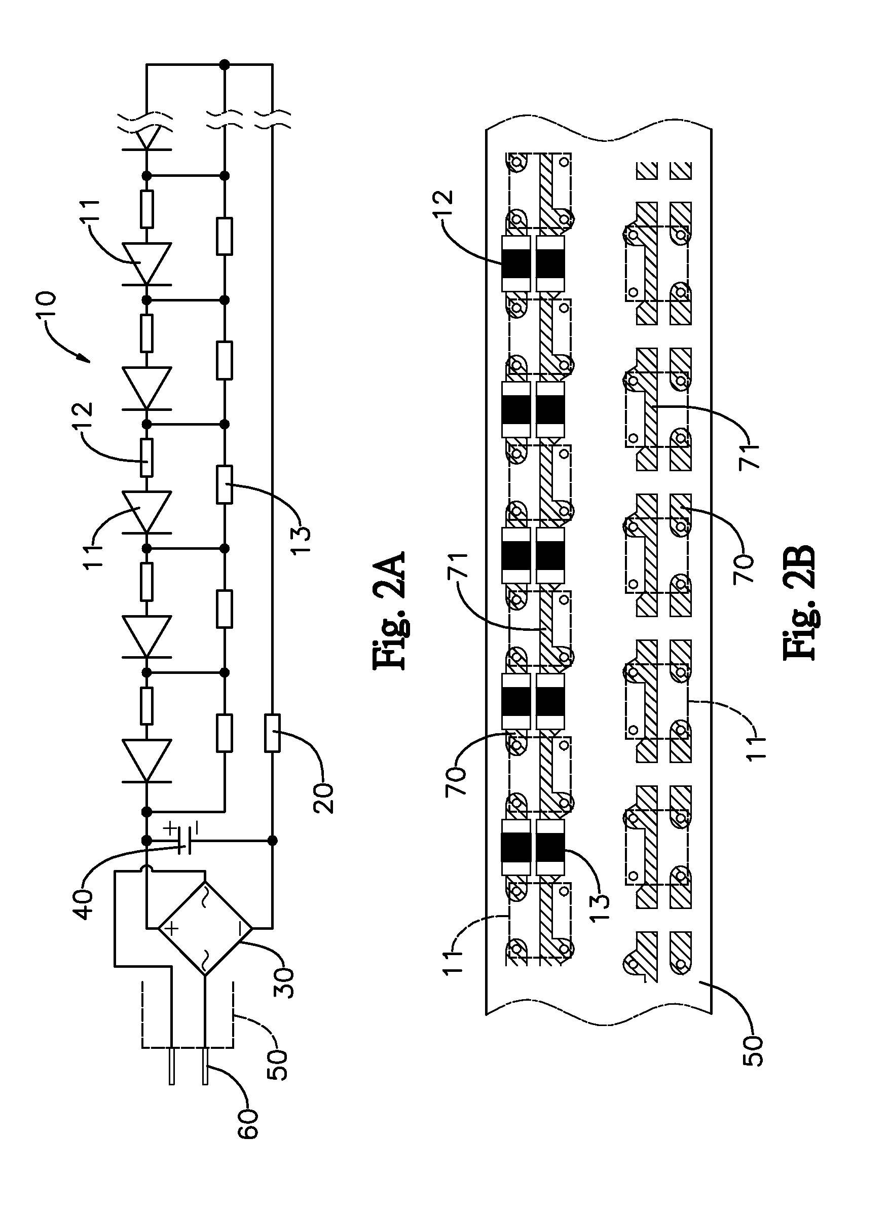
[0024]With reference to the drawings from FIGS. 2A to 6C, the present invention provides a circuit structure of light-emitting diode (LED) lamp which comprises constituent components described below.

[0025]At least one LED lamp assembly 10 consists of a plurality of LEDs 11, a plurality of serially-connected resistors 12, and a plurality of by-pass resistors 13. The plurality of LEDs 11 is connected in series with each other. Each of the serially-connected resistors 12 is set to correspond to and in serial connection with an end of each of the LEDs 11. A plurality of by-pass resistors 13 are connected in series with each other and each of the by-pass resistors 13 is connected, in parallel, to two ends of a combination of each LED 11 and the serially-connected resistor 12 connected thereto. The at least one LED lamp assembly 10 can be a single assembly 10 of LED lamps or includes a plurality of LED lamp assemblies 10 that are connected in parallel with each other.

[0026]A current-limit...


PUM


Abstract

A circuit structure of light-emitting diode (LED) lamp includes a combination of at least one LED lamp assembly, a current-limit resistor, a bridge rectifier, a capacitor set, a circuit board, and an electrical connector, by which each LED of at least one LED lamp assembly is at one end in series with a serially-connected resistor individually and then each serial-connected by-pass resistor is in parallel with the former-mentioned electrical structure to form a LED lamp assembly. The present invention provides a better solution which conventional LED lamp cannot be configured with a high voltage power supply. Further, the hardware lay-out of the circuit structure allows for direct connection with an external power source of AC 100-380V, which is fed through the bridge rectifier for regulation and conversion into direct current to be directly coupled to and used by the LED lamp assembly without a voltage-down transformer.

Description

BACKGROUND OF THE INVENTION[0001]1. Field of the Invention[0002]The present invention is related to a circuit structure of light-emitting diode (LED) lamp, and more particularly to a structure of a combination of at least one LED lamp assembly, a current limit resistor, a bridge rectifier, a capacitor assembly, a circuit board, and an electrical connector, which allows electrical current to flow through a by-pass resistor for continuously powering of the remaining LED lamps when one of LEDs within the serially-connected LED lamps is interrupted by a burned-out resistor so as to provide a better solution of being convenient to use, lighting performance, and significantly reducing total power consumed by the serially-connected LED lamps and is thus applicable to various circuit structure of LED lamps or the likes.[0003]2. Description of Prior Art[0004]Recently, light-emitting diode (LED) lamps are prevailing due to the concept of energy saving and are thus considered a practice for li...

Claims


Application Information

Patent Timeline
IPC IPC(8): H01J7/44
CPCF21K9/00F21K9/17Y02B20/348H05B33/0821F21Y2103/003F21Y2101/02F21K9/23F21K9/27F21Y2103/10F21Y2115/10H05B45/40Y02B20/30
Inventor CHEN, HUI SANWANG, CHIH TSAI
Owner CHEN HUI SAN
Why Eureka
Try Eureka