
Method for correcting stereoscopic image, stereoscopic display device, and stereoscopic image generating device

a stereoscopic image and generating device technology, applied in the field of stereoscopic image correction, can solve the problems of method inability to cope, disturb stereoscopic viewing, increase the tired feeling of stereoscopic viewing, etc., and achieve the effect of reducing crosstalk and maintaining display quality

Active Publication Date: 2011-07-14
TRIVALE TECH
View PDF10 Cites 38 Cited by
  • Summary
  • Abstract
  • Description
  • Claims
  • Application Information

AI Technical Summary

Benefits of technology

"The present invention provides a method for improving the quality of stereoscopic images by reducing crosstalk, which is a type of interference between left and right images. The method involves detecting the range of crosstalk and the crosstalk amount on the left or right image, and using this data to create a smooth slope of the image within and outside of the crosstalk range. The image is then gamma-converted to create a corrected image with reduced crosstalk. This method helps to maintain display quality and improve the overall quality of stereoscopic images."

Problems solved by technology

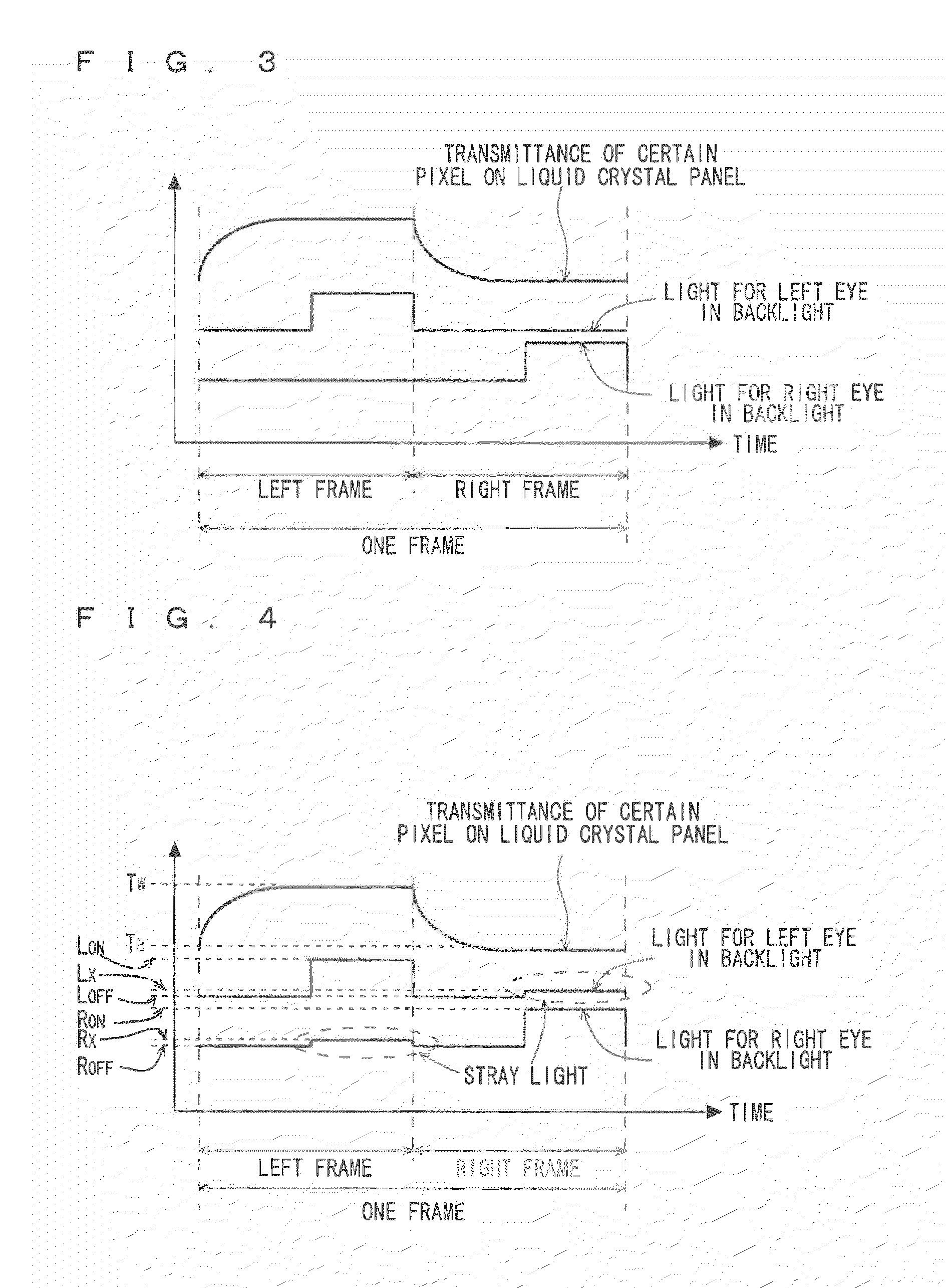
When the crosstalk is present, an image is mixed on a portion where the image is not originally seen, and a false image (hereinafter, a ghost) is viewed, thereby disturbing stereoscopic viewing and increasing tired feeling of the stereoscopic viewing.
Japanese Patent Application Laid-Open No. 2001-298754 discloses a crosstalk correcting method in the case where the crosstalk amount is simply a constant-times larger, and this method cannot cope with the case where a complicated crosstalk amount such as liquid crystal delay occurs.
Since the lowest luminance of an input image is raised to a level of a maximum crosstalk amount, entire contrast is remarkably deteriorated, and thus display quality is deteriorated.

Method used


Image

  • Method for correcting stereoscopic image, stereoscopic display device, and stereoscopic image generating device
  • Method for correcting stereoscopic image, stereoscopic display device, and stereoscopic image generating device
  • Method for correcting stereoscopic image, stereoscopic display device, and stereoscopic image generating device

Examples


first preferred embodiment

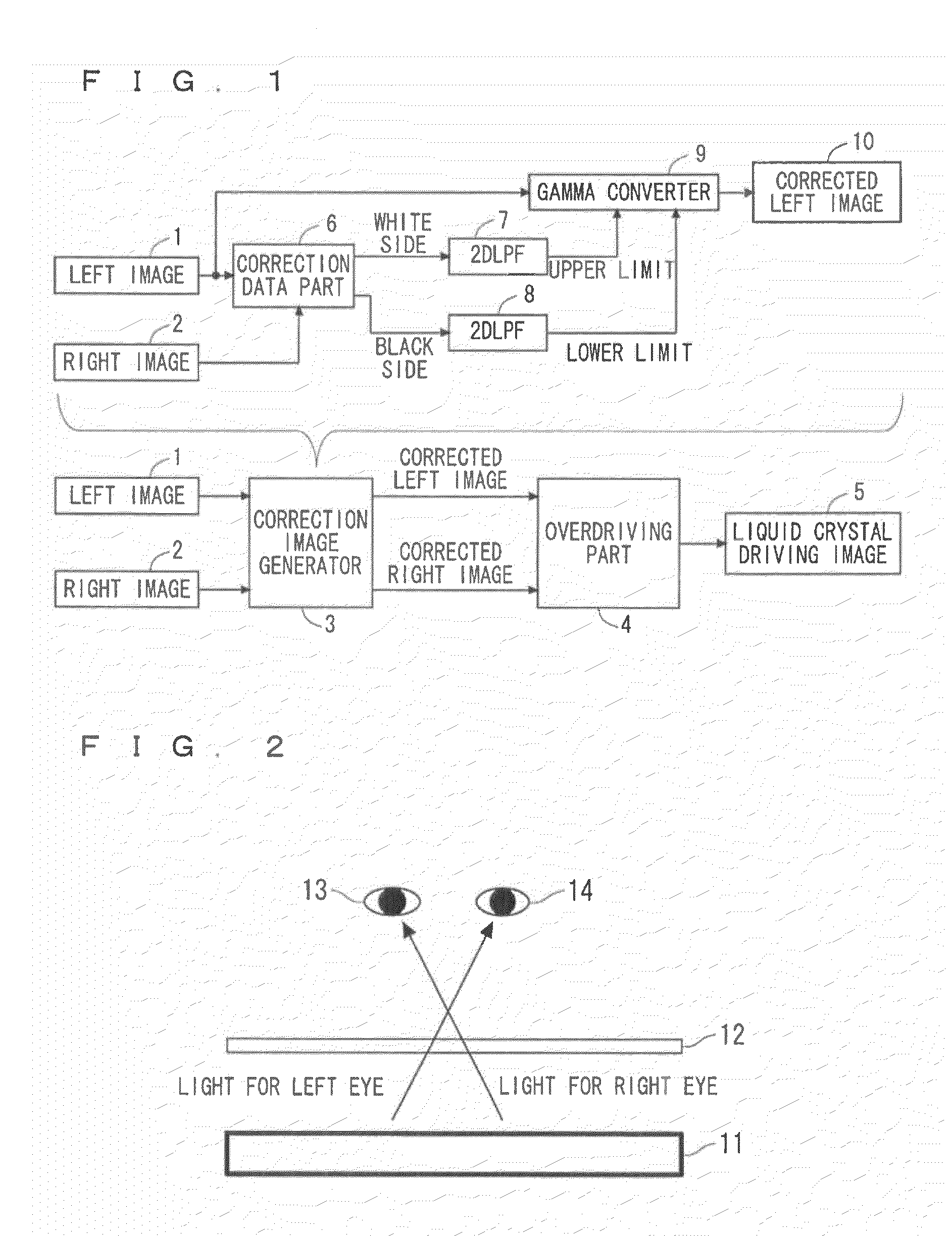
[0054]FIG. 1 is a block diagram illustrating a process for correcting and generating a stereoscopic image according to a first preferred embodiment of the present invention. As shown in FIG. 1, a left image 1 and a right image 2 are corrected by a correction image generator 3. After the corrected left image and right image undergo an overdrive process in an overdriving part 4, they are displayed as a liquid crystal driving image 5 and thus are stereoscopically displayed. The correction image generator 3 corrects a stereoscopic image displayed based on the left image 1 and the right image 2. A correction data part 6 detects a range of crosstalk and a crosstalk amount generated on the left image 1 or the right image 2 as black-side correction data where a low gradation side is a black side and as white-side correction data where a high gradation side is a white side based on crosstalk characteristic data (FIGS. 19 to 22, described later) obtained based on gradation of the inputted lef...

second preferred embodiment

[0098]In the first preferred embodiment, the process in the 2DLPFs needs the heaviest load. In a second preferred embodiment, the load of the process in the 2DLPFs is reduced. The method will be described below.

[0099]FIG. 38 is a block diagram illustrating one example of a correction image generator according to the second preferred embodiment of the present invention. Since the other constitutions and operations are similar to those in the first preferred embodiment shown in FIG. 1, the description thereof will not be given. FIG. 38 illustrates the block diagram where a left image 29 is corrected, but the similar process is also performed on a right image 30.

[0100]As shown in FIG. 38, the left image 29 and the right image 30 pass through prefilters 31 and 32. The prefilters 31 and 32 are described in detail later. The left image 29 and the right image 30 that passed through the prefilters 31 and 32 are inputted into a correction data part 33, and are divided into white-side correct...

third preferred embodiment

[0106]In the first and second preferred embodiments, both the upper limit value (white-side correction data) and the lower limit value (black-side correction data) are used as limit values to be inputted into the gamma converters 9 and 40.

[0107]As is defined in CIE 1976 L*(⅓-squares of the luminance), a luminosity factor of human eyes is sensitive to a slight difference at low luminance (luminance difference). For this reason, even when a little crosstalk occurs on the white side, visual recognition of the white side is not as difficult as the black side. Therefore, even when crosstalk is present on the white side, if the level of the crosstalk is allowable, the above-described process for operating the upper limit value can be omitted. As a result, the operating amount can be greatly reduced.

[0108]On the other hand, for example, TN (twist nematic) liquid crystal that is widely used has a responsive property such that response from white to black is much faster than response from bl...


PUM


Abstract

An object of the invention to provide a method for maintaining display quality as much as possible and reducing a crosstalk amount. A method for correcting stereoscopic images according to the present invention has (a) at least one of a step of detecting a range of crosstalk and a crosstalk amount occurring on a left image or a right image as black-side correction data, and a step of detecting the range of crosstalk and the crosstalk amount as white-side correction data, based on crosstalk characteristic data, (b) at least one of a step of making the black-side correction data into lower-limit data, and a step of making the white-side correction data into upper-limit data; and (c) a step of gamma-converting the left image or the right image based on at least one of the lower-limit data and the upper-limit data.

Description

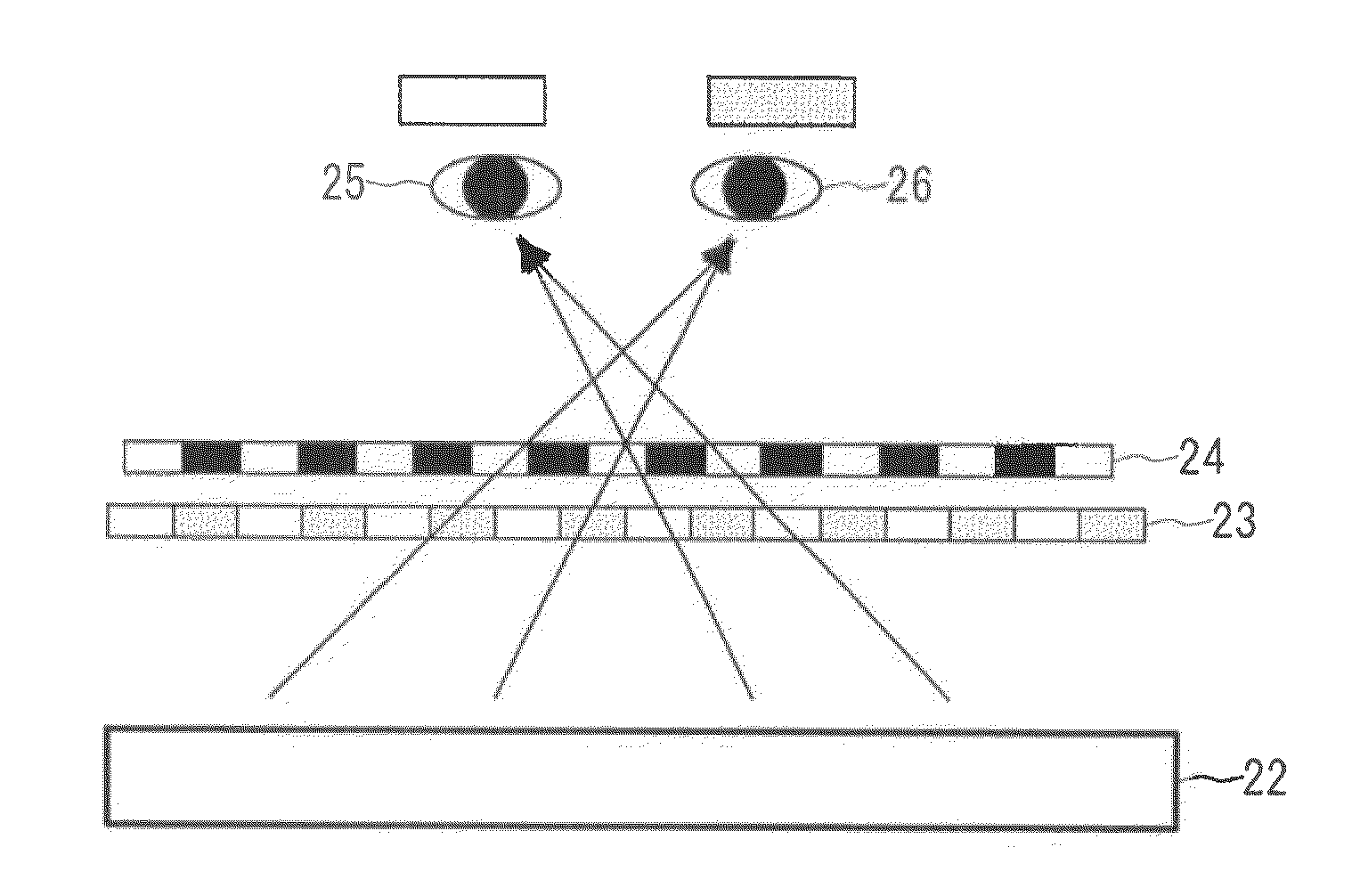
BACKGROUND OF THE INVENTION[0001]1. Field of the Invention[0002]The present invention relates to a method for correcting stereoscopic images in which stereoscopic images are corrected, a stereoscopic display device and a stereoscopic image generating device using the method for correcting stereoscopic images.[0003]2. Description of the Background Art[0004]Conventionally, stereoscopic devices adopting various systems that enable stereoscopic viewing with naked eyes and that use a special pair of eyeglasses are put to practical use. A method for enabling stereoscopic viewing with naked eyes includes holography, a method for controlling light reaching viewer's right and let eyes using a parallax barrier or a lenticular lens provided to a surface of a liquid crystal panel, and a method for controlling light reaching viewer's right and left eyes in a time division system by combining backlight having directivity of outgoing light (hereinafter, directional backlight) and a liquid crystal ...

Claims


Application Information

Patent Timeline
Patent Type & Authority Applications(United States)
IPC IPC(8): G06K9/00G06T15/00H04N13/125
CPCG09G3/003H04N13/0438H04N13/0018G09G2340/16H04N13/341H04N13/122H04N13/125
Inventor ISHIGUCHI, KAZUHIRO
Owner TRIVALE TECH
Learn More