In-vivo imaging device with double field of view and method for use

a technology of in-vivo imaging and double field of view, applied in the field of imaging systems, can solve the problems of cost effectiveness, blockage of the region between 5° and 10°, and achieve the effect of high-quality imag

Inactive Publication Date: 2011-07-14
GIVEN IMAGING LTD
View PDF37 Cites 113 Cited by
  • Summary
  • Abstract
  • Description
  • Claims
  • Application Information

AI Technical Summary

Benefits of technology

[0013]Use of such a system may enable a conventional imaging array to be used, without the need to use unduly small pixel sizes, since the pixels in the central area of the imaging array receive a more highly magnified image than those in the periphery, such that the same uniform, moderate pixel density, can resolve the finer details of the object in the region of high magnification.

Problems solved by technology

In prior art systems, since except for very high volume use, it is not cost effective to produce a dedicated array with smaller pixel size in the center region where the high magnification image falls, the whole imaging array typically has a pixel size commensurate with the high magnification image resolution.
However, careful design of the two lens sets can limit this blocked region to between 5° and 10°.

Method used


Image

  • In-vivo imaging device with double field of view and method for use
  • In-vivo imaging device with double field of view and method for use
  • In-vivo imaging device with double field of view and method for use

Examples


examples

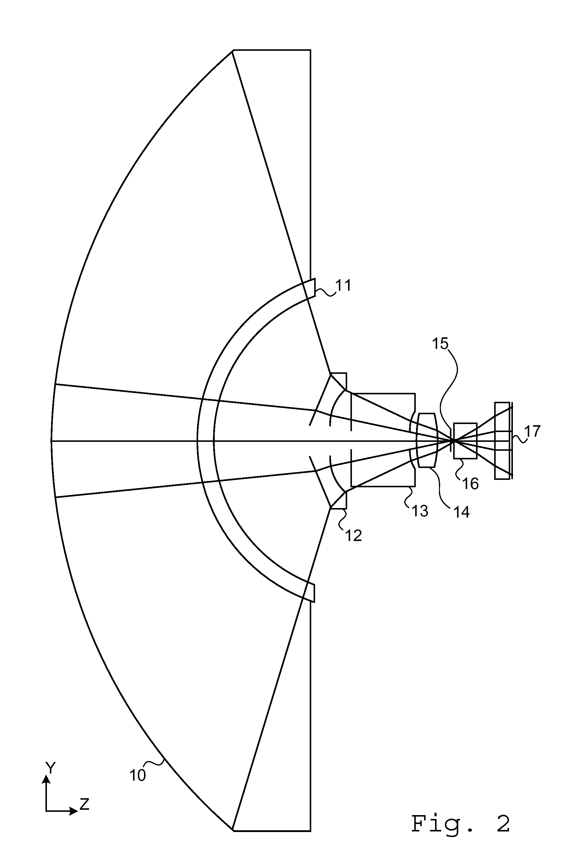
[0041]Reference is now made to Table I, which provides specifications and prescription data for one exemplary implementation of the low magnification, wide field of view section of an optical system such as is described in FIG. 2 of this application. Other implementations are possible. The results of the design iteration are given from the program output without rounding. This exemplary lens assembly contains 4 lenses and 3 elements without optical power, whose optical parameters have been optimized using the ZEMAX® optimization program. This exemplary system has been designed to provide a 130° total field of view. The effective focal length is 1.24823 mm, and the back focal length to the imager plane is 0.53858 mm. The total optical track length is 10.699 mm, and the paraxial working f / number is 5.51225. All dimensions are in mm.

TABLE ISurfaceTypeR ° C.ThicknessMaterialDiameterConic CoefficientOBJSTANDARD17.55Water26.778801EVENASPH5.926490.5Polycarb.11.02−0.11481212EVENASPH5.462233...


PUM


Abstract

An in-vivo imaging device incorporating a double field of view imaging system, having a wide field of view with moderate magnification, and a narrow field of view with substantially higher magnification, axially superimposed thereon. A single imaging array is used for both fields of view. At least some of the optical elements are shared between both of the two different field of view imaging systems. The imaging elements for the high magnification system, being of substantially smaller diameters than those of the low magnification system, are disposed coaxially with the imaging elements of the low magnification system, and can thus use the same imaging array without the need for deflection mirrors, beam combiners or motion systems. Their location on the axis of the low magnification system means that a small part of the imaging plane, around its central axis, is blocked out by the high magnification components.

Description

PRIOR APPLICATION DATA[0001]The present application claims the benefit of prior U.S. provisional application No. 61 / 294,232, entitled “IN VIVO IMAGING DEVICE WITH DOUBLE FIELD OF VIEW”, filed on Jan. 12, 2010, incorporated by reference herein in its entirety.FIELD OF THE INVENTION[0002]The present invention relates to the field of imaging systems capable of generating images at a number of magnifications in a static configuration, especially for use in systems requiring magnifications widely different by one or more orders of magnitude.BACKGROUND OF THE INVENTION[0003]There exist many applications where an imaging system is intended to generate a general view of the surveilled region, but where it is desired to obtain a “microscope view” having a substantially higher magnification, when a region of interest is detected in the general view. An example of such a requirement exists in the endoscopic or capsule-based imaging of the interior of a gastro-intestinal tract.[0004]Autonomous ...

Claims


Application Information

Patent Timeline
Patent Type & Authority Applications(United States)
IPC IPC(8): H04N7/18
CPCA61B1/00016G02B23/243A61B1/041
Inventor PASCAL, AMITBEZDIN, HAIM
Owner GIVEN IMAGING LTD
Why Eureka
Try Eureka