Illumination Device Comprising a Light-Emitting Diode

a technology of light-emitting diodes and illumination devices, which is applied in semiconductor devices for light sources, lighting and heating apparatus, and light support devices. it can solve the problems of increasing manufacturing costs, reducing thermal conduction, and only dissipating heat produced during led operation, and achieves good heat transfer and simple means.

Inactive Publication Date: 2011-07-14
OSRAM GMBH
View PDF3 Cites 9 Cited by
  • Summary
  • Abstract
  • Description
  • Claims
  • Application Information

AI Technical Summary

Benefits of technology

[0013]If parts which can be touched by the user are coated, a housing or heat sink for example, said parts may be in contact with live parts, the holder for example, without any danger existing for the user on touching said parts.
[0014]Such layers can be easily applied by using different coating methods, the PECVD method for example, to different substrates, in particular to metals and glass.
[0016]It is expedient if the layer has a preferably constant thickness of at least 1 μm and at most 3 μm, preferably of approximately 2 μm. This layer thickness can be simply applied but is also sufficiently great to ensure that no accidentally uncoated regions are produced. In this situation, a layer is regarded as constant when the maximum deviation from the average layer thickness does not exceed 5%. If translucent components such as for example an optical system for light guidance or the bulb of an LED lamp are to be coated, the visible light permeability is not too greatly reduced at said layer thicknesses.
[0017]The invention has a particularly advantageous effect when the illumination device has at least a base and / or at least a bulb enclosing the light-emitting diode and the support element and is thus designed as an LED lamp. With regard to these lamps, the support element and the light-emitting diodes are enclosed by base and bulb, as a result of which the dissipation of the heat is rendered more difficult. The additional or alternative use of a heat sink visible from the outside and the provision of the bulb with ventilation slots in order to dissipate the heat is disadvantageous because these measures adversely affect the appearance of the lamp in an undesirable manner and promote the deposition of dust and dirt. Through the use of the coating according to the invention, a simpler and more effective distribution of the heat in the LED lamp can be accomplished, which facilitates the dissipation of said heat.
[0012]According to the invention, a support element can for example be provided with a layer according to the invention, on which the light-emitting diodes can be arranged such that a particularly good dissipation of the heat from the light-emitting diodes is achieved in that said heat is dissipated directly both to the side and also downwards. Particularly in the case of a support element having a relatively low thermal conductivity, for example a plastic circuit board, the lateral dissipation of the heat is advantageous because said heat can thus be distributed over a large area. Because the layer is in addition electrically insulating, the terminals of the LED are automatically insulated with respect to one another regardless of the material of the support element. A particularly advantageous embodiment thus also becomes possible in that a metallic support element, which thus has a good thermal conductivity, for example a copper or aluminum support, can be used, by means of which the heat dissipation from the LED can be effected particularly advantageously.
[0019]In this situation it is particularly advantageous if the layer is arranged on the outside of the bulb because this is exposed to the ambient air and can dissipate the heat to the latter.
[0020]Advantageously, the bulb is coated at least in part with a conversion layer for the at least partial conversion of at least one wavelength of the radiation delivered by the LED into a different wavelength. The light color of the LED lamp can be set by this means. In contrast to a conversion layer which is arranged directly in the region of the LED, a conversion layer arranged on the bulb is subjected to lesser loads, in particular loads of a thermal nature.
[0021]Advantageously, the conversion layer is arranged on the inside of the bulb because it is protected there against ambient influences.
[0022]By providing on the bulb at least one layer which is largely impermeable to UV radiation, in particular which absorbs and / or reflects UV radiation, in particular the layer having a high thermal conductivity which is designed as a layer largely impermeable to UV radiation, UV light originating from the LED which is harmful to the user is reliably screened. In the case of a reflective layer, the UV radiation can continue to be directed back onto the conversion layer situated further inwards, thereby increasing the efficiency of the LED lamp.

Problems solved by technology

A disadvantage of illumination devices in accordance with the prior art and here in particular of LED lamps is however the fact that the heat produced during operation of the LED can only be inadequately dissipated.
Although a support element having a high thermal conductivity is frequently chosen, made of copper or aluminum for example, in order to dissipate the heat directly from the LEDs, an insulating layer must however in this case be arranged between LED and support element, said insulating layer diminishing the thermal conduction and increasing the manufacturing costs.

Method used


Image

  • Illumination Device Comprising a Light-Emitting Diode
  • Illumination Device Comprising a Light-Emitting Diode

Examples


Embodiment Construction

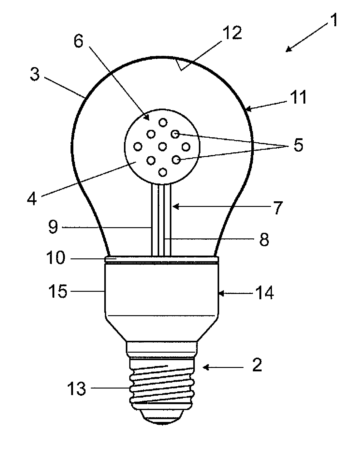
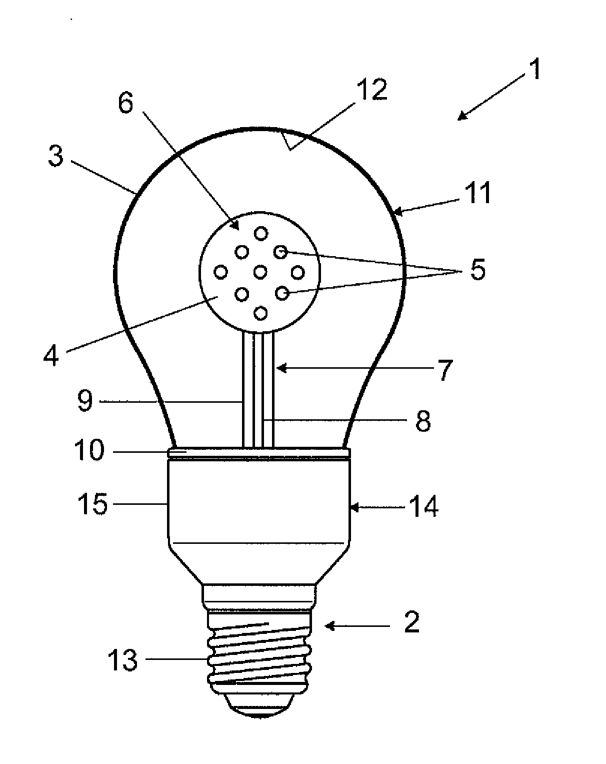
[0029]The invention will be described in detail in the following with reference to an exemplary embodiment. As an example of an illumination device 1 according to the invention the figure shows an LED lamp 1 having a base 2, a bulb 3 and a support element 4, on which are arranged light-emitting diodes (LED) 5.

[0030]The support element 4 is formed from aluminum and coated with a nonconducting layer 6 consisting of tetrahedral amorphous carbon (so-called diamond-like carbon, DLC) having a thickness of approximately 2 μm. This layer is both electrically insulating and also outstandingly thermally conductive (more than 600 W / mK, typically approx. 1000 W / mK). This means that the LEDs 5 have an outstanding thermal connection to the support element 4 and are also insulated electrically from the latter. The high thermal conductivity of the DLC layer 6 simultaneously has the effect that the heat being given off by the LEDs 5 is distributed along the surface of the support element 4 and good ...


PUM


Abstract

An illumination device (1) having comprising at least one support element (4) and at least one light-emitting diode (5) arranged on the support element (4), characterized in that wherein at least one of the plurality of components (2, 3, 4, 7, 10) of the illumination device (1) intended for heat dissipation from the light-emitting diode (5), in particular the support element (4), is provided at least in part with an electrically insulating layer (6, 11) having a high thermal conductivity, formed at least in part from a carbon compound, in particular from amorphous carbon, in particular tetrahedral amorphous carbon.

Description

AREA OF TECHNOLOGY[0001]The invention relates to an illumination device having at least one support element and at least one light-emitting diode arranged on the support element.PRIOR ART[0002]Illumination devices having light-emitting diodes are increasingly being used in general lighting on account of their high efficiency and falling manufacturing costs. On account of their small size, the actual light-emitting diodes are in this situation mostly arranged on a support element, on which in addition can be arranged further elements such as for example other light-emitting diodes, feed lines or circuits.[0003]In this situation, the LED lamps which are preferably employed in order to replace existing conventional lamps such as for example incandescent lamps or fluorescent lamps without needing to make changes here to the luminaire or the holder represent a special form of the illumination devices. With regard to LED lamps, the support element with one or more light-emitting diodes is...

Claims


Application Information

Patent Timeline
Patent Type & Authority Applications(United States)
IPC IPC(8): F21V29/00
CPCF21V29/004F21Y2101/02F21V3/00F21K9/135F21V29/86F21V29/006F21K9/56F21V29/506F21Y2111/001F21V29/85F21K9/232F21K9/64F21Y2115/10F21Y2107/00F21V29/51F21V29/70F21V29/00
Inventor HOCKEL, JENS FLORIAN
Owner OSRAM GMBH
Why Eureka
Try Eureka