Illumination apparatus with a heat sink

a technology of heat sink and heat sink, which is applied in the direction of light and heating apparatus, semiconductor devices for light sources, transportation and packaging, etc., can solve the problem that the heat produced during the operation of led is only able to be dissipated insufficient amounts, and achieve the effect of simple and cost-effective production and handling

Inactive Publication Date: 2011-07-14
OSRAM GMBH
View PDF5 Cites 8 Cited by
  • Summary
  • Abstract
  • Description
  • Claims
  • Application Information

AI Technical Summary

Benefits of technology

[0009]As at least one component of the illumination apparatus provided for heat dissipation, particularly the heat sink, has an emission coefficient of more than 0.75, preferably of more than 0.8, particularly preferably of more than 0.9 at least in sub-regions on at least one free surface, the discharge of radiant heat by these components, i.e. for example by the heat sink, to the surroundings is improved so that with the same surface more heat may be discharged to the surroundings and / or with the same heat output the surface of the component may be reduced.
[0028]It may also be advantageous if the light-permeable element and the heat sink have a different color as this, for example, illustrates to the user the boundary between a component (heat sink) which is likely to be heated up during operation and a relatively cool component in comparison (light-permeable element, for example the bulb) and thus the user is reliably able to avoid contact with the hot component.

Problems solved by technology

A drawback with illumination apparatuses according to the prior art, however, and in this case, in particular, in LED lamps is that the heat produced during the operation of the LED is only able to be dissipated inadequately.

Method used


Image

  • Illumination apparatus with a heat sink
  • Illumination apparatus with a heat sink
  • Illumination apparatus with a heat sink

Examples


Embodiment Construction

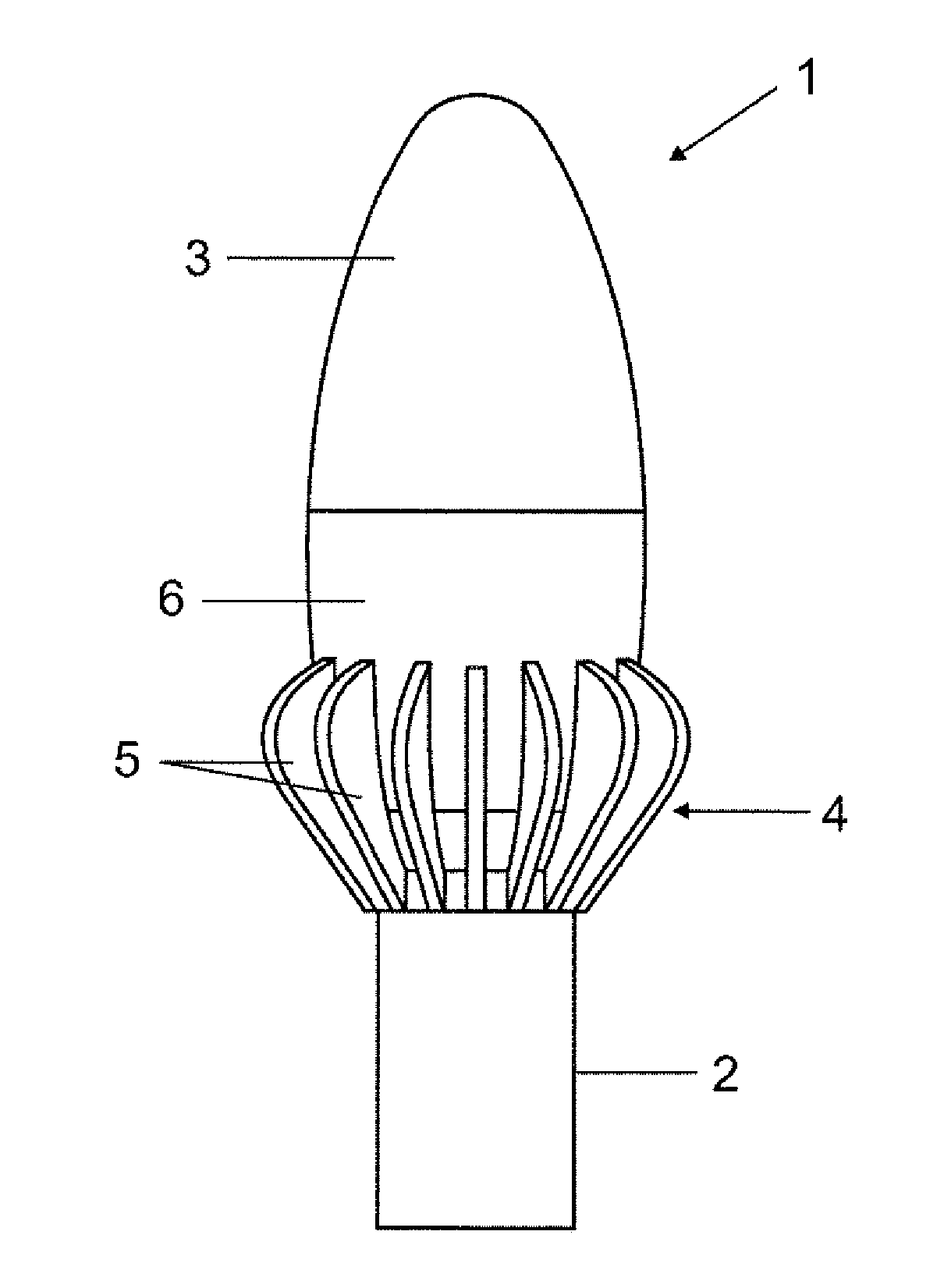
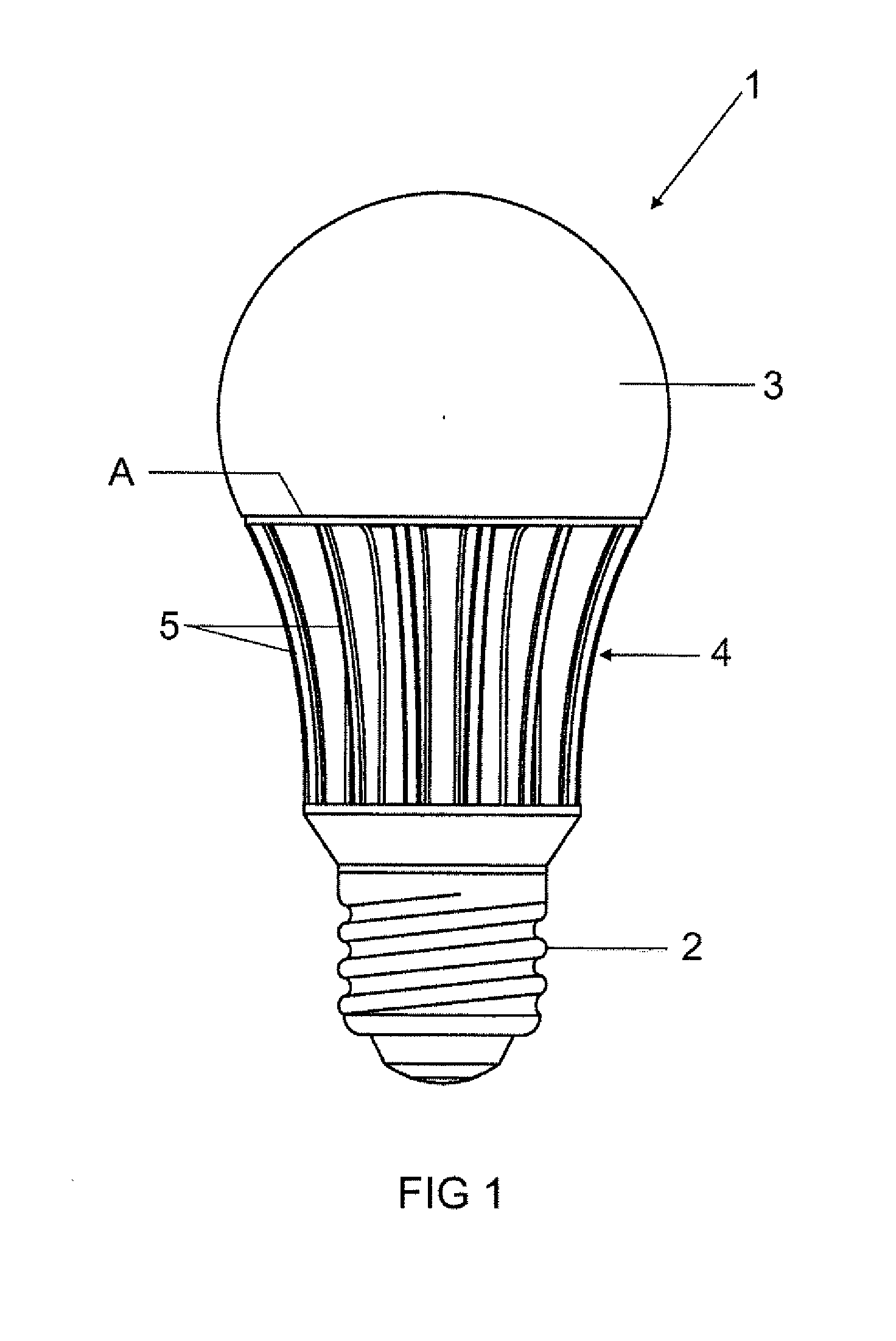
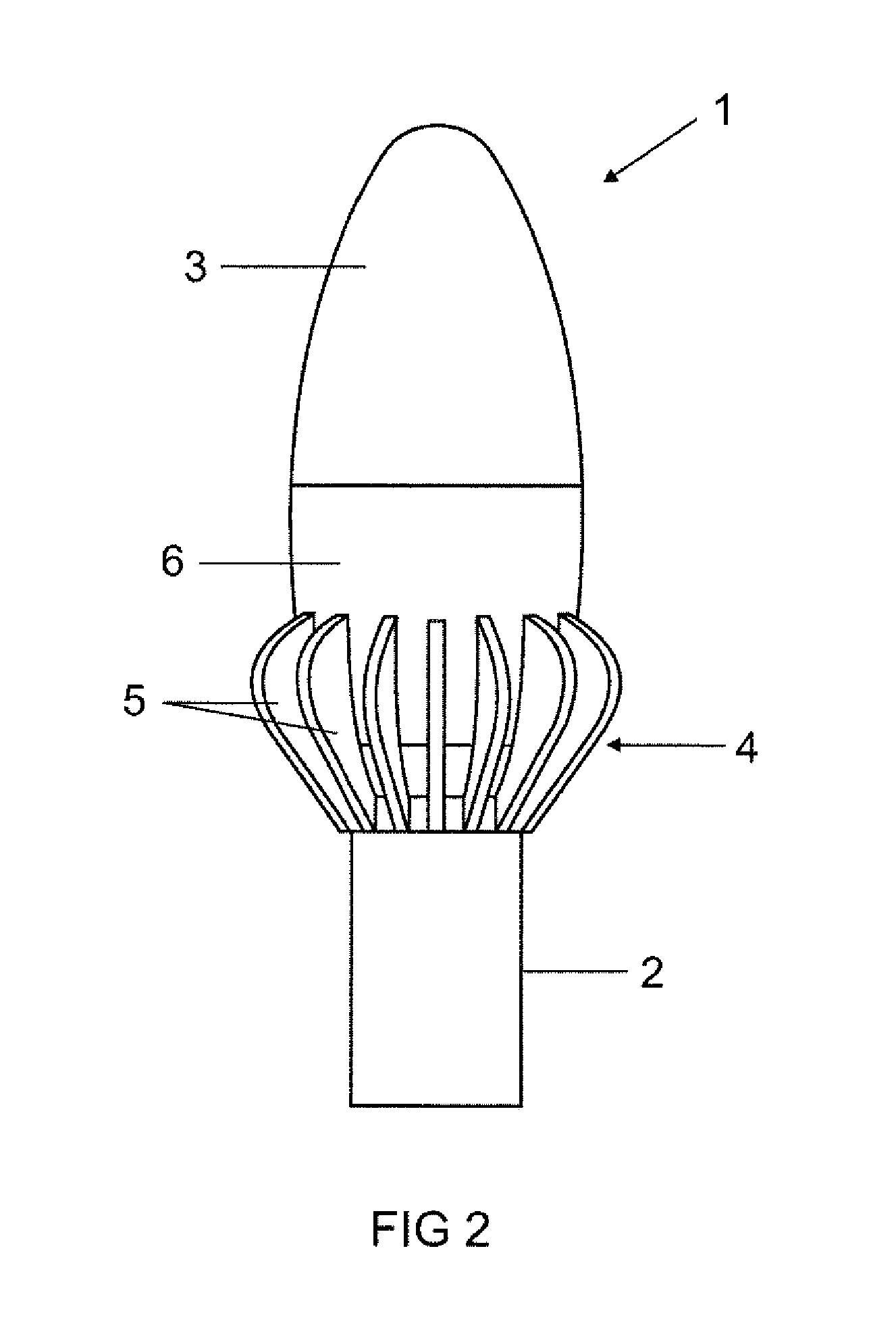
[0006]The object of the present invention is, therefore, to provide an illumination apparatus having at least one light-emitting diode (LED) and at least one heat sink for cooling the light-emitting diode, in which the cooling is optimized, so that a smaller heat sink is used and / or the thermal load of the LED is reduced and thus the life and efficiency thereof are increased.

[0007]This object is achieved by the characterizing features of claim 1.

[0008]Particularly advantageous embodiments are set forth in the dependent claims.

[0009]As at least one component of the illumination apparatus provided for heat dissipation, particularly the heat sink, has an emission coefficient of more than 0.75, preferably of more than 0.8, particularly preferably of more than 0.9 at least in sub-regions on at least one free surface, the discharge of radiant heat by these components, i.e. for example by the heat sink, to the surroundings is improved so that with the same surface more heat may be discharg...


PUM

PropertyMeasurementUnit
power densitiesaaaaaaaaaa
emissivityaaaaaaaaaa
light-permeableaaaaaaaaaa

Abstract

An illumination apparatus is provided. The illumination apparatus may include at least one light-emitting diode; and at least one heat sink for cooling the light-emitting diode, wherein at least one component of the illumination apparatus provided for thermal discharge has an emission coefficient of more than 0.75.

Description

TECHNICAL FIELD[0001]The invention relates to an illumination apparatus having at least one light-emitting diode (LED) and at least one heat sink for cooling the light-emitting diode.PRIOR ART[0002]Illumination apparatuses having light-emitting diodes are increasingly used for general illumination due to the high level of efficiency and reduced production costs. Generally, in this case the light-emitting diodes are operatively connected thermally to a heat sink in order to be able to discharge the heat produced during their operation.[0003]LED lamps represent a particular form of illumination apparatus which are LED-based illumination apparatus, and which are subject to spatial restrictions and thus are preferably designed in one piece. LED lamps are generally used to replace existing conventional lamps, such as for example incandescent lamps or fluorescent lamps, without having to undertake alterations to the light or the lampholder. In LED lamps, therefore, a conventional cap is g...

Claims


Application Information

Patent Timeline
Patent Type & Authority Applications(United States)
IPC IPC(8): F21V29/00
CPCF21V3/00F21Y2101/02F28F1/14F21K9/135F28F2245/06F21V29/77F28F13/18F21K9/232F21Y2115/10
Inventor BREIDENASSEL, NICOLEHOFMANN, MARKUS
Owner OSRAM GMBH
Why Eureka
Try Eureka