Cutting Insert Having Cutting Edges with Recessed Portions

a cutting insert and recessed portion technology, which is applied in the direction of turning tools, milling equipment, turning apparatus, etc., can solve the problems of limiting the range of applications of cutting inserts, cutting inserts are liable to break at the cutting edges, etc., and achieves the effect of withstanding greater cutting forces and high metal removal rates

Active Publication Date: 2011-07-14
ISCAR LTD
View PDF14 Cites 48 Cited by
  • Summary
  • Abstract
  • Description
  • Claims
  • Application Information

AI Technical Summary

Benefits of technology

This structure of the recessed cutting edge portions has proven to be advantageous in milling operations, especially rough milling of metallic work pieces at high metal removal rates. On the one hand the interrupted cutting edge causes chip splitting and on the other hand the curved sections provide a robust interrupted cutting edge which can withstand greater cutting forces without breaking in comparison with interrupted cutting edges in which the recessed cutting edge portions do not have this curved structure.
In accordance with a preferred embodiment, the central section has a first radius of curvature and each side section has a second radius of curvature, the first radius of curvature being larger than the second radius of curvature. This particular structure provides further strengthening of the interrupted cutting edge.

Problems solved by technology

However, in such prior art cutting inserts the form of the recessed portions are generally not optimized for all-round performance and in many cases the cutting inserts are liable to break at the cutting edges during milling operations.
Moreover, the general geometry of prior art cutting inserts having cutting edges with recessed portions is in many cases limited to the form of flat slabs with opposing flat parallel rake and base surfaces, or simple positive geometries, thereby limiting the range of applications of the cutting inserts.

Method used


Image

  • Cutting Insert Having Cutting Edges with Recessed Portions
  • Cutting Insert Having Cutting Edges with Recessed Portions
  • Cutting Insert Having Cutting Edges with Recessed Portions

Examples


Embodiment Construction

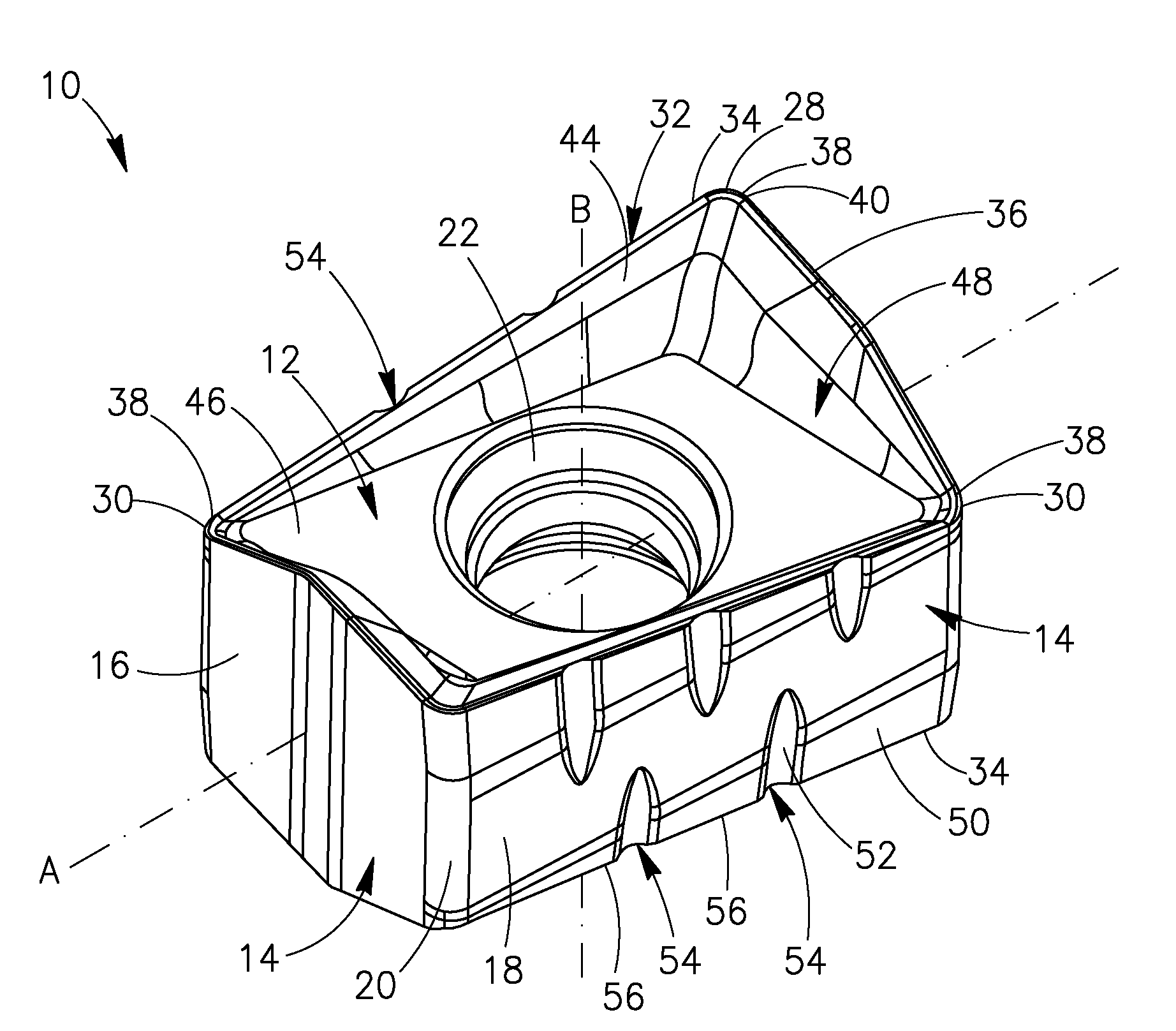
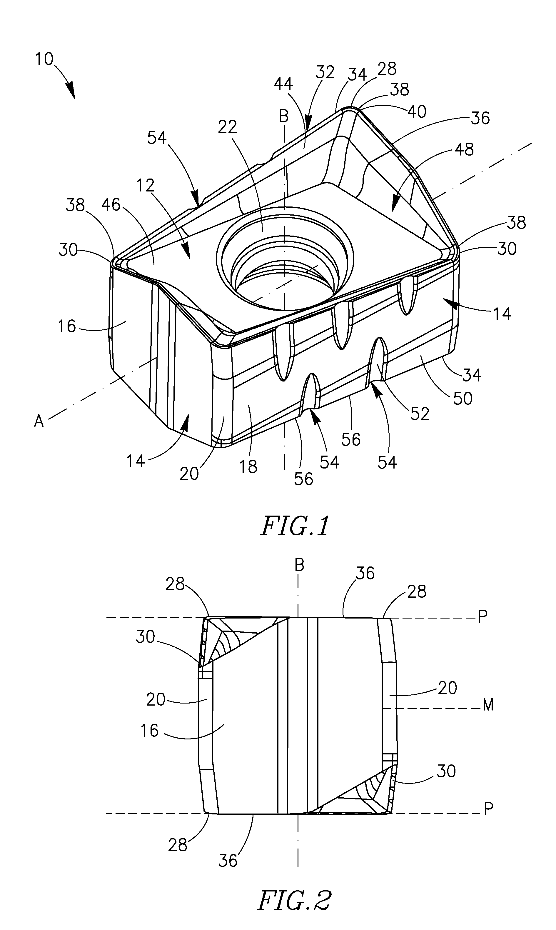
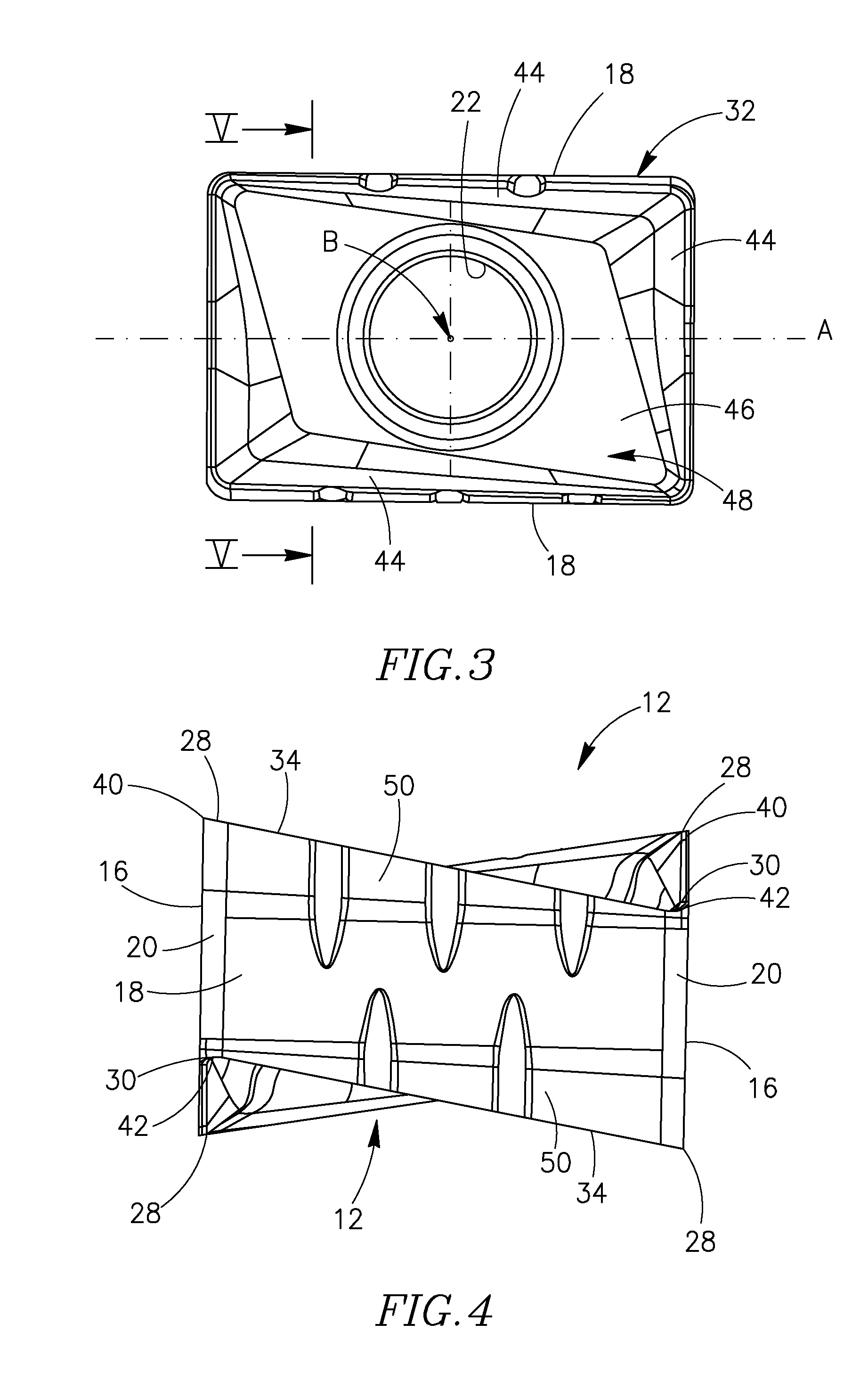
Attention is first drawn to FIGS. 1 to 7, showing a cutting insert 10 with respect to which the present invention will be described and illustrated. However, the present invention relates to properties of the cutting edges of cutting inserts and while it is certainly applicable to the cutting insert shown in the figures, it is by no means restricted to this cutting insert which is used herein as a non-binding example. The cutting insert 10 is indexable, and is preferably manufactured by form-pressing or by injection molding and sintering carbide powders. The cutting insert 10 comprises two identical opposing end surfaces 12 of a generally rectangular shape in an end view of the cutting insert 10.

A peripheral side surface 14 extends between the two opposing end surfaces 12 and comprises two opposed identical minor side surfaces 16, two opposed identical major side surfaces 18 of a generally parallelogrammatic shape, and corner side surfaces 20 located between adjacent minor and major...


PUM

PropertyMeasurementUnit
radius of curvatureaaaaaaaaaa
interior angleaaaaaaaaaa
widthaaaaaaaaaa

Abstract

A cutting insert has a cutting edge formed at the intersection of a side surface an end surface. Recesses formed in the side surface interrupt the cutting edge at recessed cutting edge portions. Each recessed cutting edge portion has, in an end view of the cutting insert, a curved central section located between two curved side sections. The central section has a first radius of curvature and each side section has a second radius of curvature, the first radius of curvature being larger than the second radius of curvature.

Description

FIELD OF THE INVENTIONThe present invention relates to cutting inserts having cutting edges with recessed portions.BACKGROUND OF THE INVENTIONCutting inserts having cutting edges with recessed portions, such as notches or grooves, are generally used for rough milling machining of metallic work pieces at high metal removal rates.There are many examples disclosed in the art of cutting inserts having cutting edges with recessed portions. Triangular, square, round, and rectangular shaped cutting inserts are disclosed, respectively, in U.S. Pat. No. 3,574,911; U.S. Pat. No. 3,636,602; U.S. Pat. No. 3,922,766; and U.S. Pat. No. 4,936,714.However, in such prior art cutting inserts the form of the recessed portions are generally not optimized for all-round performance and in many cases the cutting inserts are liable to break at the cutting edges during milling operations. Moreover, the general geometry of prior art cutting inserts having cutting edges with recessed portions is in many cases...

Claims


Application Information

Patent Timeline
Patent Type & Authority Applications(United States)
IPC IPC(8): B23C5/20B23B27/16B23C5/16
CPCB23C5/06B23C5/202B23C2200/128B23C2200/205B23C2210/203B23C2210/48Y10T407/1924B23C2220/60B23C5/20Y10T407/1962Y10T407/245Y10T407/23Y10T407/235B23C2210/486
Inventor SMILOVICI, CAROLATAR, OSAMA
Owner ISCAR LTD
Why Eureka
Try Eureka