Hole Cutter with Chip Egress Aperture

a hole cutter and aperture technology, applied in the field of hole cutters, can solve the problems of not being configured to allow the chips or dust generated during cutting to flow through the aperture and away from the interiors of the blade body, and affecting so as to facilitate the flow of chips, and facilitate the effect of chip flow

Active Publication Date: 2011-07-14
BLACK & DECKER INC
View PDF86 Cites 42 Cited by
  • Summary
  • Abstract
  • Description
  • Claims
  • Application Information

AI Technical Summary

Benefits of technology

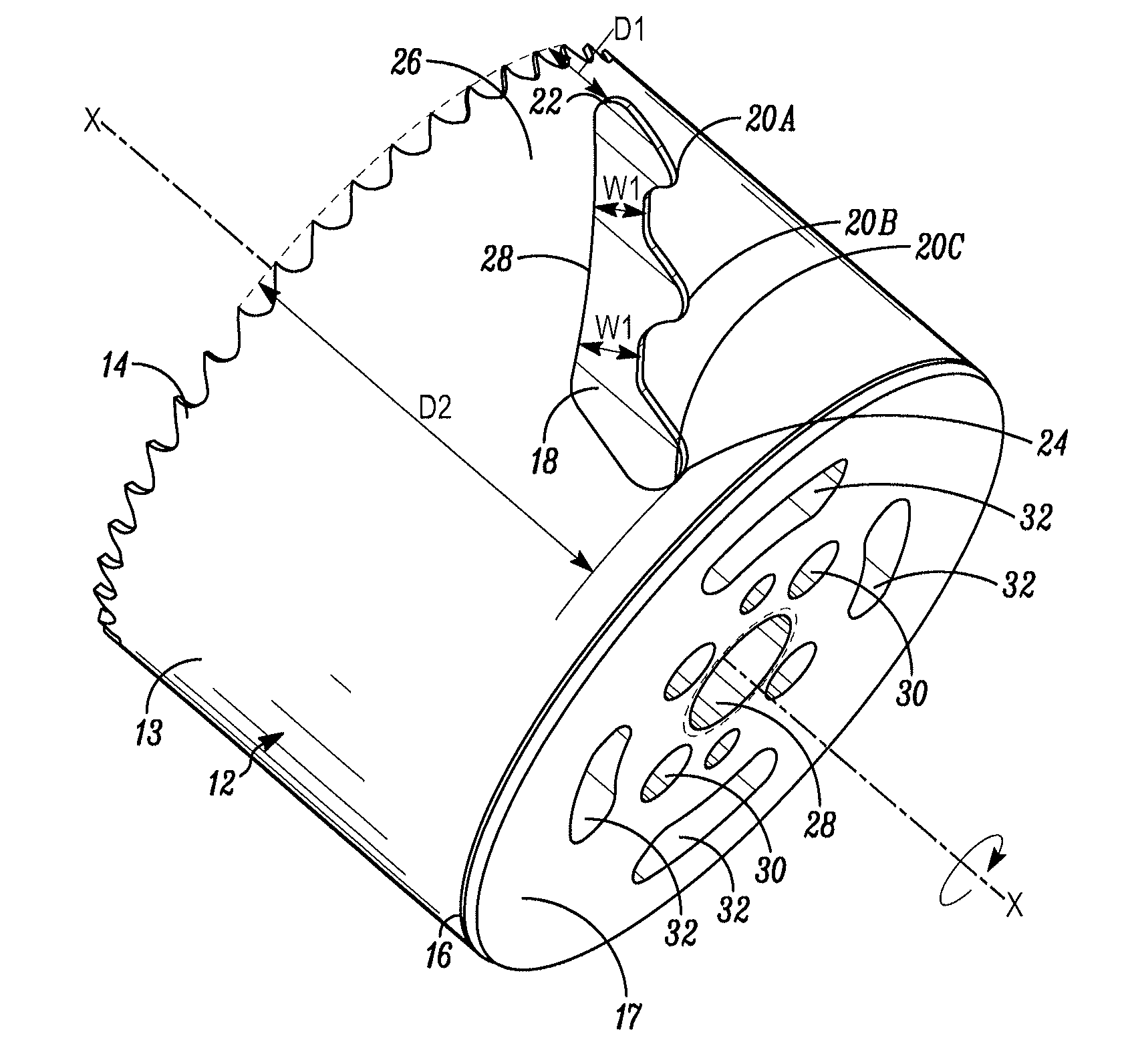
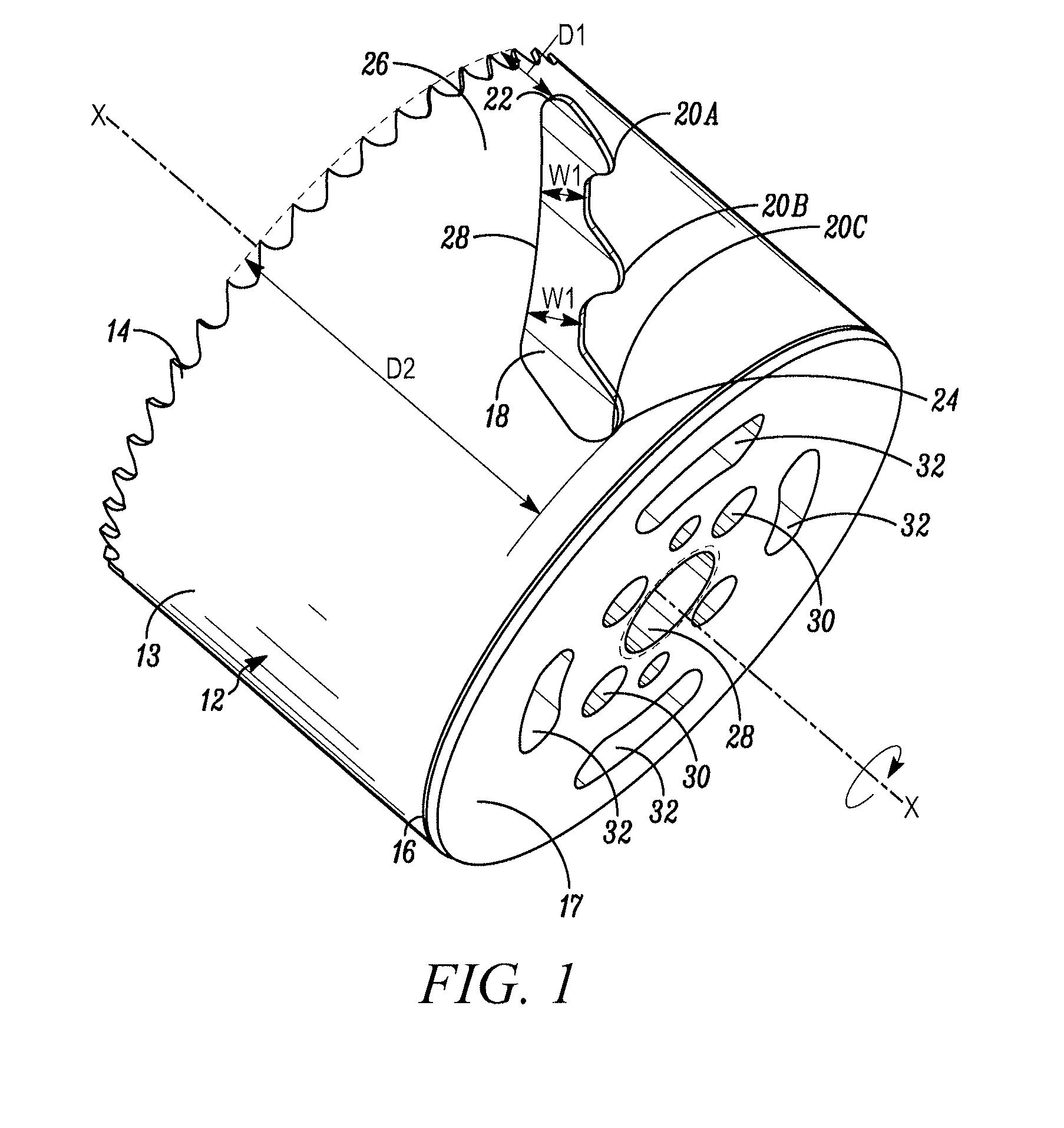
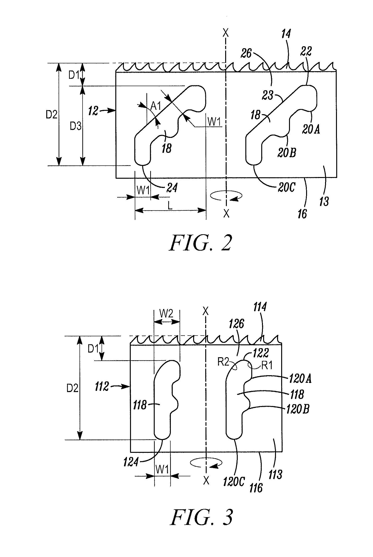
[0016]One advantage of the hole cutters of the present invention is that the first ends of the axially-elongated slots or like means are axially spaced adjacent to the cutting edge a first distance within the range of about 15 / 100 inch to about ⅜ inch, and the second ends of the slots or like means are axially spaced from the cutting edge a second distance that is greater than the first distance. The second distance is at least about 1½ inches. As a result, the chips flowing from the cutting edges within the interiors of the blade bodies are allowed to flow into the slots or like means and / or through the slots or like means to, in turn, prevent the collection of such chips within the interiors of the blade bodies and / or at an interface between the blade bodies and work pieces. The relatively close spacing of the first end of each slot or like means to the cutting edge (about 15 / 100 inch to about ⅜ inch) facilitates the flow of chips into the slot or like means, and the depth of the slot or like means from the cutting edge (at least about 1½ inches) facilitates the flow of chips into and / or through the slot or like means for a wide variety of work piece thicknesses. Yet another advantage of the hole cutters of the present invention is that they define significant slot area to cylindrical blade body circumference ratios of at least about 0.1, and in many sizes of hole cutters, at least about 0.15 or 0.2, which in turn gives rise to substantial slot areas per given blade body diameters. As a result, the relatively large areas of the slots or like means, in combination with the close placement of the first or inlet ends of the slots or like means relative to the cutting edges of the hole cutters, facilitates the flow of chips into and / or through the slots, and in turn prevents the collection of such chips within the interiors of the hole cutters. The relatively large slot areas facilitate in preventing the slots from becoming clogged with chips and / or allow the slots themselves to retain a significant volume of chips, that otherwise would be trapped within the interiors of the blade bodies. Accordingly, the hole cutters of the present invention provide significantly improved chip removal or egress from the interiors of the blade bodies in comparison to prior art hole cutters which, in turn, can lead to significantly improved cutting speeds and / or blade life. Another advantage of some currently preferred embodiments of the present invention is that the slots or like means are oriented at acute angles relative to the axes of the hole cutters to facilitate the flow of chips up and / or through the slots and thus away from the interiors of the blade bodies. Yet another advantage of some currently preferred embodiments of the present invention is that the first or inlet ends of the slots define edge surfaces that slope away from the cutting edge in a direction opposite the cutting direction of the hole cutters to further facilitate the flow of chips up and / or through the slots and thus away from the interiors of the blade bodies.

Problems solved by technology

One of the drawbacks encountered with prior art hole cutters is that chips or dust, particularly when cutting wood, collects within the interiors of the hole cutters between the work piece slugs and the caps on the non-working ends of the hole cutters.
The apertures formed in the side walls of the blade bodies are designed to allow the insertion of screw drivers or like tools to remove work piece slugs, but are not configured to allow the chips or dust generated during cutting to flow through the apertures and away from the interiors of the blade bodies.
The collection of chips and dust within the interiors of the blade bodies and / or at the interfaces of the blade bodies and work pieces can significantly reduce the cutting efficiency and overall cutting speed and / or blade life of such hole cutters.
Although many prior art hole cutters include one or more apertures formed through the side walls of the blade bodies, the apertures are not configured to facilitate the flow of chips from the interiors of the blade bodies into and / or through the apertures.

Method used


Image

  • Hole Cutter with Chip Egress Aperture
  • Hole Cutter with Chip Egress Aperture
  • Hole Cutter with Chip Egress Aperture

Examples


Embodiment Construction

[0024]In FIG. 1, a hole cutter embodying the present invention is indicated generally by the reference numeral 10. The term “hole cutter” is used herein to mean a tool that cuts holes in work pieces, such as wood or metal work pieces, and includes without limitation hole saws. The hole cutter 10 includes a blade body 12 defining a side wall 13. The blade body 12 is shown in FIG. 2 in its flattened state; however, as shown in FIG. 1, the blade body 12 is rolled or otherwise formed into a substantially cylindrical shape to form the hole cutter 10. As shown in FIG. 1, the side wall 13 extends around an axis of rotation “X” of the hole cutter 10 to define the substantially cylindrical blade body 12. One end of the blade body 12 is provided with a cutting edge 14 oriented substantially perpendicular to the axis of rotation X, and the opposing end of the blade body defines a rim 16. As shown in FIG. 1, a cap 17 is fixedly secured, such as by welding, to the rim 16 to enclose the respectiv...


PUM

PropertyMeasurementUnit
diameteraaaaaaaaaa
acute angleaaaaaaaaaa

Abstract

A hole cutter has a substantially cylindrical blade body defining a blade body circumference, a cutting edge formed on one end of the blade body, and an axially-elongated slot formed through the substantially cylindrical blade body. The axially-elongated slot is configured to receive chips flowing from the cutting edge within the interior of the blade body and (i) into the slot, and/or (ii) through the slot, to prevent the collection of such chips within the interior of the blade body and/or at an interface between the blade body and work piece. The axially-elongated slot defines a first end adjacent to the cutting edge, a second end axially spaced further from the cutting edge, and a slot area. The hole cutter further defines a total slot area to blade body circumference ratio within the range of about 0.1 to about 0.3 depending on the size of the hole cutter.

Description

[0001]This application is a continuation-in-part of co-pending U.S. patent application Ser. No. 12 / 687,078 filed Jan. 13, 2010, which is incorporated by reference in its entirety as if fully set forth herein.FIELD OF THE INVENTION[0002]The present invention relates to hole cutters, and more particularly, to hole cutters with apertures formed in the side walls thereof.BACKGROUND INFORMATION[0003]A typical prior art hole cutter includes a cylindrical blade body defining a plurality of saw teeth on the cutting edge of the blade body, and one or more apertures formed through an intermediate portion of the blade body. Typically, smaller diameter hole cutters have fewer apertures formed through the blade bodies, and larger diameter hole cutters have more apertures formed through the blade bodies. The apertures formed through prior art hole cutter blade bodies may define a variety of different configurations to facilitate inserting a tool into the apertures, such as a screw driver, to remo...

Claims


Application Information

Patent Timeline
Patent Type & Authority Applications(United States)
IPC IPC(8): B23B51/04
CPCY10T408/895B23B51/0406B23B2260/072Y10T408/8953Y10T408/896B23B51/04B23B51/0467B23B51/0453
Inventor NOVAK, JOSEPH THOMASGREEN, MATTHEW CHRISTOPHER
Owner BLACK & DECKER INC
Why Eureka
Try Eureka