Multi-gap interferometric sensors

a technology of interferometer and sensor, applied in the field of improved extrinsic fabryperot interferometer (efpi) sensor, can solve the problems of equipment and structure being subject to extreme demands, equipment and structure being exposed to high temperatures, and affecting the operation and longevity of equipment and structures

Active Publication Date: 2011-07-14
BAKER HUGHES INC
View PDF17 Cites 18 Cited by
  • Summary
  • Abstract
  • Description
  • Claims
  • Application Information

AI Technical Summary

Problems solved by technology

Unfortunately, the environment presented deep into the borehole can place extreme demands upon the equipment and structures disposed therei

Method used


Image

  • Multi-gap interferometric sensors
  • Multi-gap interferometric sensors
  • Multi-gap interferometric sensors

Examples


Embodiment Construction

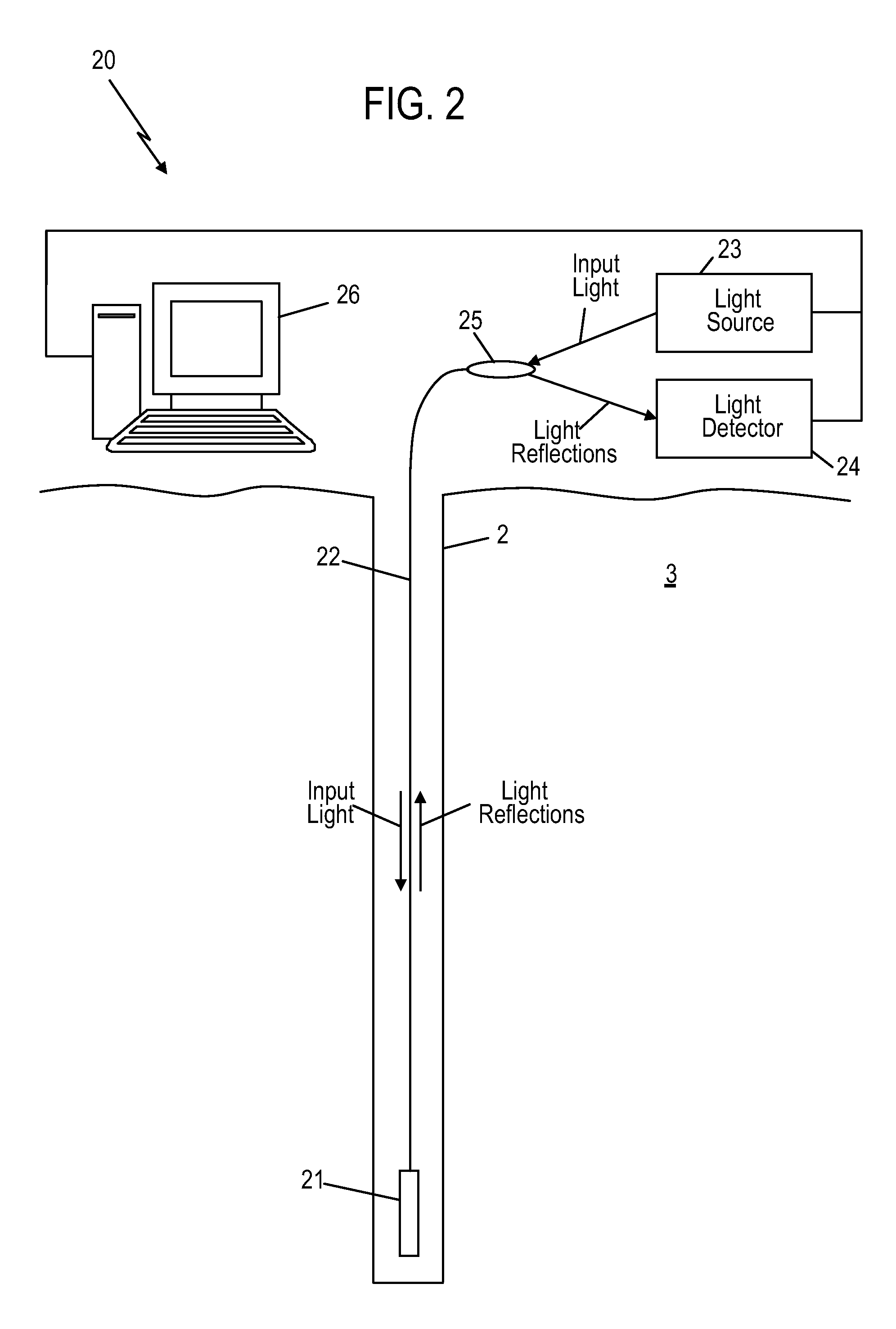
[0018]Reference may now be had to FIG. 2. FIG. 2 illustrates an exemplary embodiment of an EFPI sensor system 20. The EFPI sensor system 20 includes an EFPI sensor 21 configured to be disposed in a borehole 2 penetrating the earth 3. Being configured for operation in the borehole 2 includes being operable at the high temperatures and pressures encountered downhole.

[0019]Still referring to FIG. 2, the EFPI sensor 21 is coupled to surface optoelectronics by way of a communication optical fiber 22. In an alternative embodiment, some or all of the optoelectronics can be disposed downhole. The surface optoelectronics include a light source 23, such as a laser diode, and a light detector 24. The light source 23 is configured to transmit input light to the EFPI sensor 21 while the light detector 24 is configured to receive and measure light reflections from the sensor 21. An optical coupler 25 is configured to couple the light source 23 and the light detector 24 to the communications optic...


PUM


Abstract

An apparatus for estimating a property includes a hollow core tube and an input light guide disposed at least partially within hollow core tube. The apparatus also includes a second gap disposed within the hollow core tube and separated from the input light guide by an air gap width. The second gap is formed of a first solid material and has a second gap width. The apparatus also includes a third gap disposed at least partially within the hollow core tube and being further from the input light guide than the second gap. The third gap is formed of a second solid material and has a third gap width.

Description

CROSS-REFERENCE TO RELATED APPLICATIONS AND PRIORITY CLAIM[0001]This application claims the benefit of U.S. Provisional Application Ser. No. 61 / 294,240, entitled “IMPROVED EFPI SENSOR”, filed Jan. 12, 2010, under 35 U.S.C. §119(e), and which is incorporated herein by reference in its entirety.BACKGROUND OF THE INVENTION[0002]1. Field of the Invention[0003]The present invention relates to an improved Extrinsic Fabry-Perot Interferometer (EFPI) sensor. More particularly, the EFPI sensor is configured to be disposed in a borehole penetrating the earth.[0004]2. Description of the Related Art[0005]In exploration and production of hydrocarbons, it is often necessary to drill a borehole into the earth to gain access to the hydrocarbons. Equipment and structures, such as borehole casings for example, are generally disposed into a borehole as part of the exploration and production. Unfortunately, the environment presented deep into the borehole can place extreme demands upon the equipment an...

Claims


Application Information

Patent Timeline
IPC IPC(8): G06F17/18G01B9/02
CPCG01D5/268G01K5/48G01K11/3206G01V8/02G01B9/02023G01B2290/25G01B9/02025E21B47/06G01D5/353G01K11/32G01L11/02G01D5/35312E21B47/12G01B9/02
Inventor CHILDERS, BROOKS A.HARMAN, ROBERT M.HOMA, DANIEL S.BECKNER, LANCE A.
Owner BAKER HUGHES INC
Why Eureka
Try Eureka