
Safety output device

a safety output and output device technology, applied in error detection/correction, program control, instruments, etc., can solve the problems of hard to detect input line errors, the noise removal method utilizing the frequency separation characteristics of the noise filter cannot completely separate foreign noise having wideband frequency components, and the normal self-diagnosis cannot be performed. , to achieve the effect of less susceptible to nois

Inactive Publication Date: 2011-07-14
KK TOSHIBA
View PDF15 Cites 20 Cited by
  • Summary
  • Abstract
  • Description
  • Claims
  • Application Information

AI Technical Summary

Benefits of technology

The invention is a safety output device for a control apparatus that can prevent output signals from affecting the operation terminal and execute safe control less susceptible to noise. It includes an output controller, normal output unit, test pattern generating unit, combination output unit, reconfiguration unit, and comparator. The device can perform self-diagnosis in parallel with the control cycle and detect any difference between the self-diagnosis pattern data to determine if there is an anomaly. This ensures the safety and reliability of the control apparatus.

Problems solved by technology

If the pulse width of a noise pulse caused by the noise and superimposed on signals on the input line 100a and the output line 100b is approximately equal to that of the self-diagnosis pulse signal, the self-diagnosis pulse signal cannot be distinguished from the noise pulse, causing a problem that a normal self-diagnosis cannot be performed.
However, a noise removal method utilizing the frequency separation characteristics of the noise filter cannot completely separate foreign noise having wideband frequency components.
Accordingly, use of the noise filter may cause overlook of a pulse signal representing an indication of a failure, or false detection of a failure.
Hence there is a problem that it is hard to detect errors of the input line 100a or the output line 100b.
Nevertheless, there is a problem that the self-diagnosis pulse signal may adversely affect behaviors of the control target 200 depending on the response performance of the operation terminal portion 13.
Moreover, in the above-described method of Japanese Patent No. 4131134 which sets an interval period known in advance as a period in which no self-diagnosis pulse signal is generated from the safety equipment, and temporally separates the operation-output step signal from the self-diagnosis signal received from the external device, there is a problem that the safety control and the self-diagnosis of the input-output device cannot be executed in parallel or at any selected timing.

Method used


Image

  • Safety output device
  • Safety output device
  • Safety output device

Examples


first embodiment

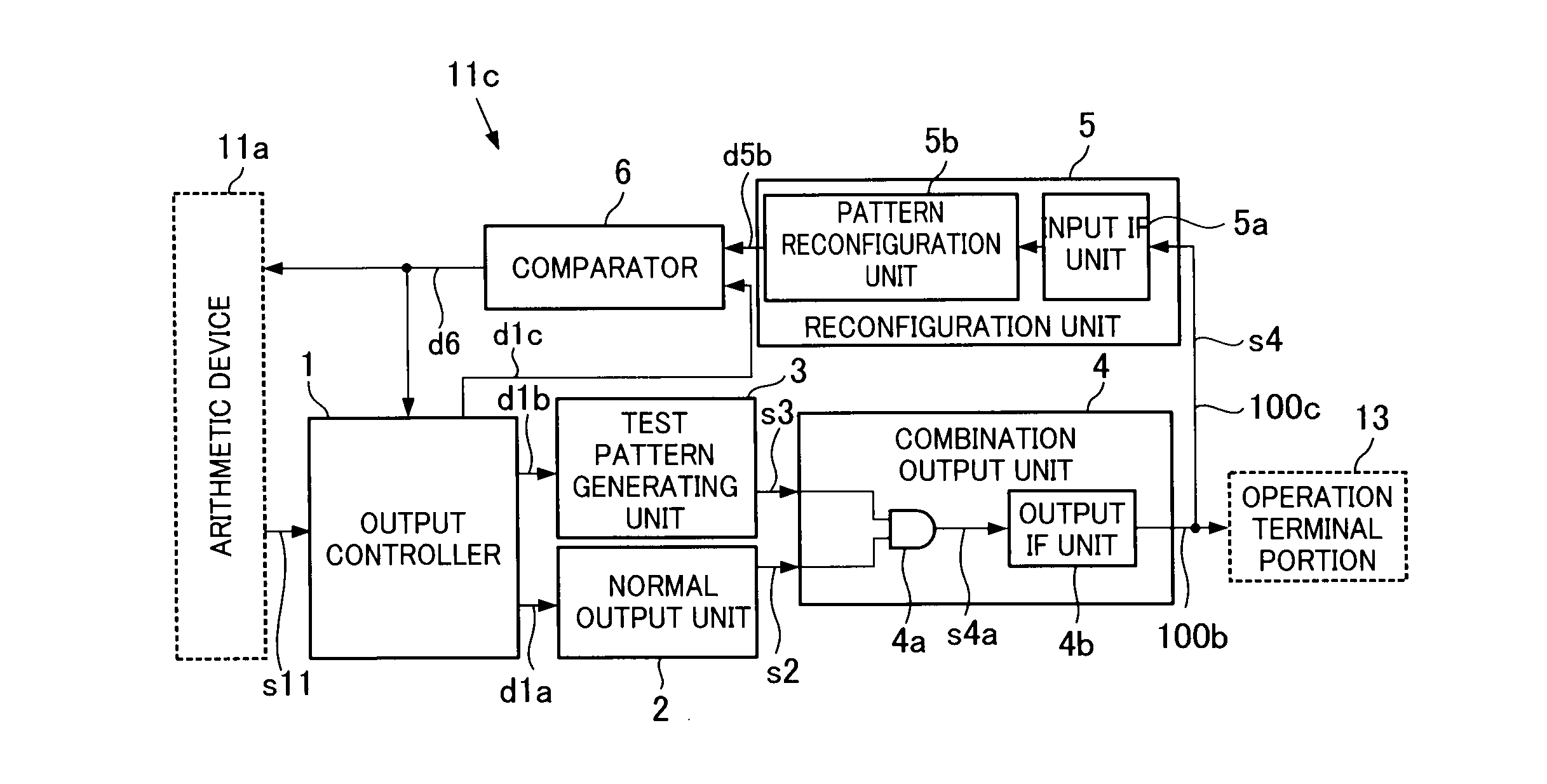
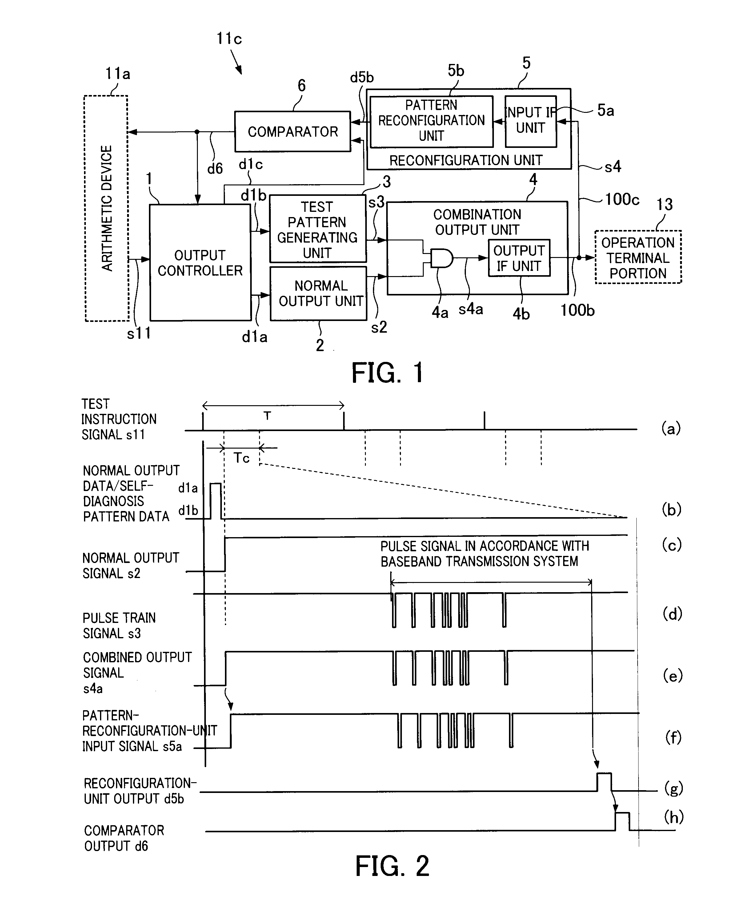
[0035]A first embodiment of a safety output device according to the invention will be described with reference to FIGS. 1 and 2.

[0036]Concerning a safety control system employing the safety output device, the same portions as those of the configuration described in FIG. 8 will be designated by the same reference numerals, and description of those portions will be omitted herein. To distinguish from the conventional output device 11c described in FIG. 8, the safety output device of the invention will be hereinafter referred to as a safety output device 11c.

[0037]In FIG. 1, the safety output device 11c of the invention is provided to a control apparatus (not shown) configured to send an operation terminal portion 13 normal output data sent from an arithmetic device 11a of the control apparatus and also to perform a self-diagnosis.

[0038]The safety output device 11c includes an output controller 1, a normal output unit 2, a test pattern generating unit 3, and a combination output unit ...

second embodiment

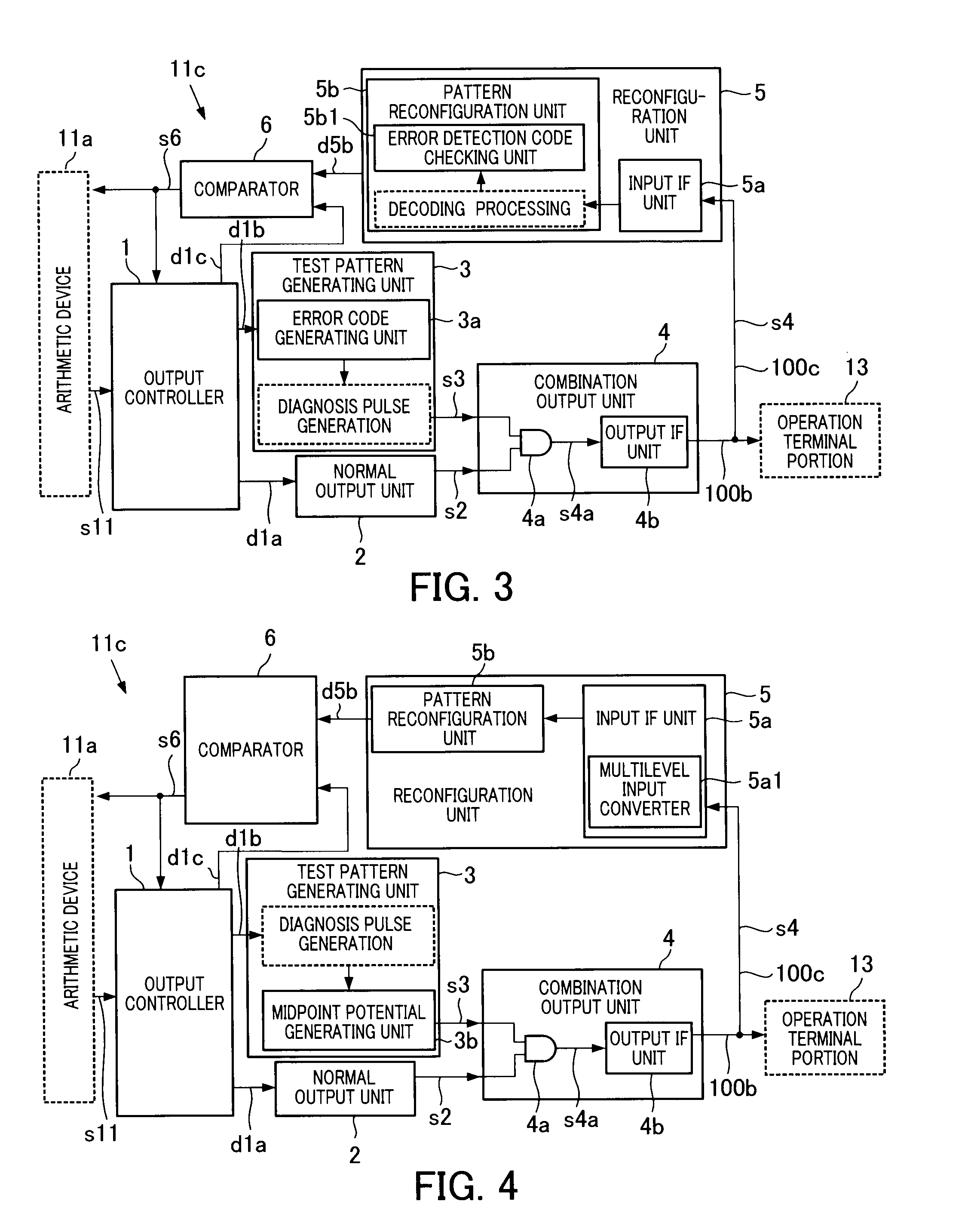
[0060]Next, a safety output device according to a second embodiment will be described with reference to FIG. 3. Portions in the second embodiment which are the same as those shown in FIG. 1 will be designated by the same reference numerals, and description of those portions will be omitted.

[0061]The second embodiment is different from the first embodiment in the following respects. Specifically, in the first embodiment, the test pattern generating unit 3 generates only the self-diagnosis pattern data. In contrast, in the second embodiment, the test pattern generating unit 3 is provided with an error code generating unit 3a to attach an error detection code to the self-diagnosis pattern data. Moreover, the pattern reconfiguration unit 5b of the reconfiguration unit 5 is provided with an error detection code checking unit 5b1 configured to check the error detection code attached and decoded.

[0062]Another difference is that the comparator 6 compares the preset self-diagnosis pattern da...

third embodiment

[0073]Next, a safety output device according to a third embodiment will be described with reference to FIGS. 4 and 5. Portions in the third embodiment which are the same as the portions shown in FIG. 1 will be designated by the same reference numerals, and description of those portions will be omitted.

[0074]The third embodiment is different from the first embodiment in the following respects. Specifically, the signal generated by the test pattern generating unit 3 in the first embodiment is a two-level pattern signal. In contrast, in the third embodiment, the test pattern generating unit 3 is provided with a midpoint potential generating unit 3b configured to generate a multilevel signal, and the input interface unit 5a for the read-back signal is provided with a multilevel input converter 5a1 configured to convert a multilevel input signal into a two-level signal.

[0075]Specifically, the test pattern generating unit further includes the midpoint potential generating unit 3b that obt...


PUM


Abstract

A safety output includes an output controller to make an instruction to output normal output data and first self-diagnosis pattern data synchronously with a control cycle, a normal output unit to output the normal output data synchronously with the control cycle, a test pattern generating unit to encode the self-diagnosis pattern data into a pulse train signal having a pulse width not larger than a preset value and output the pulse train signal in accordance with a baseband transmission system, a combination output unit to combine the pulse train signal with the normal output signal and output the resultant signal, a reconfiguration unit to decode the inputted operation-terminal-portion output signal to reconfigure the operation-terminal-portion output signal as second self-diagnosis pattern data, and a comparator to compare the first self-diagnosis pattern data with the second self-diagnosis pattern data to judge the presence or absence of a difference.

Description

CROSS REFERENCE TO RELATED APPLICATION[0001]This application is based upon and claims the benefit of priority from the prior Japanese Patent Application No. 2010-5190, filed on Jan. 13, 2010, the entire contents of which are incorporated herein by reference.BACKGROUND[0002]1. Field[0003]The invention relates to an input-output device of a control apparatus that monitors and controls a plant or field equipment, or more specifically to a safety output device provided with a self-diagnosis function.[0004]2. Description of the Background[0005]A safety control system required to be highly reliable, particularly, are now equipped with a control apparatus that monitors and controls a plant, field equipment, and the like and that has a self-diagnosis function to self-diagnose a failure of the control apparatus without human help.[0006]FIG. 8 shows a configuration example of such a safety control system. In FIG. 8, a safety control system 100 includes, for example, an input terminal portion ...

Claims


Application Information

Patent Timeline
Patent Type & Authority Applications(United States)
IPC IPC(8): G06F11/263
CPCG05B19/0428G06F11/263G05B2219/24054
Inventor NAKATANI, HIROSHITOKO, MAKOTOFUKAI, EIGO
Owner KK TOSHIBA
Learn More