
Blood collection tube storage box and blood collection tube preparing apparatus

a technology for preparing apparatus and blood collection tubes, which is applied in the direction of instruments, packaging goods types, pharmaceutical product form changes, etc., can solve the problem of increasing the size of the apparatus

Inactive Publication Date: 2011-07-21
AFC MINNESOTA
View PDF16 Cites 16 Cited by
  • Summary
  • Abstract
  • Description
  • Claims
  • Application Information

AI Technical Summary

Benefits of technology

[0029]According to the invention of claim 1, the blood collection tube holding member is provided between the forward-side transferring belt and the backward-side transferring belt of the one endless transferring belt driven to rotate in the horizontal direction. The blood collection tube holding member is a guide frame formed of a rail-like or plate-like member or the like having a smoothed surface, and supports one of the lower end surfaces of the cap of the blood collection tube. The other of the opposing lower end surfaces of the cap is supported on the upper end surface of the forward-side transferring belt. Therefore, the blood collection tube is moved while sliding on the blood collection tube holding member and the forward-side transferring belt under a state in which the lower end surfaces of the cap are respectively supported on the upper end surfaces of the blood collection tube holding member and the forward-side transferring belt. The blood collection tube is transferred through bringing the upper end surface of the forward-side transferring belt and the lower end surface of the cap of the blood collection tube into contact with each other.
[0030]On the terminal end side of the blood collection tube holding member, the blood collection tube is disengaged from the blood collection tube holding member to be cantilever-supported on the upper end surface of the forward-side transferring belt. Then, the cap (head) side is inclined toward the blood collection tube holding member disengaged from the blood collection tube so that the blood collection tube falls down. Thereafter, the blood collection tube is discharged.
[0031]As described above, according to the invention of claim 1, between the forward-side transferring belt and the backward-side transferring belt of the one transferring belt, the storage box of a suspended type for supporting the lower end surfaces of the cap of the blood collection tube is formed. Therefore, the conveying device for the blood collection tube in the storage box can be structured as one conveying device for one kind of blood collection tube, and hence the number of conveying devices can be set to be requisite minimum. Further, the blood collection tube storage box is formed between the forward-side transferring belt and the backward-side transferring belt of the one transferring belt, and hence one storage box has a width of only a few centimeters. Thus, even in the case where a plurality of kinds of storage boxes are aligned with each other in order to correspond to various kinds of blood collection tubes, the entire width dimension can be advantageously and remarkably reduced in comparison with the prior art.
[0032]Further, according to the invention of claim 1, there is adopted a mechanism for discharging the leading blood collection tube through isolating the leading blood collection tube from the other blood collection tubes, and the first stopper and the second stopper are provided. The first stopper is capable of moving close to and away from the front surface side of the cap of the leading blood collection tube so as to abut against the same. The second stopper is capable of moving close to and away from the gap formed between the caps of the leading and second blood collection tubes.
[0033]The first stopper abuts against the front surface side of the cap of the leading blood collection tube, and the second stopper enters the gap formed between the caps of the leading and second blood collection tubes. Under this state, the first stopper is operated to move away from the leading blood collection tube, and to disengage from the front surface side of the cap of the leading blood collection tube. Then, the leading blood collection tube is further moved ahead through being transferred while the upper end surface of the forward-side transferring belt and the lower end surface of the cap are held in contact with each other. After a while, the terminal end side of the blood collection tube holding member is disengaged. Therefore, the leading blood collection tube assumes such a posture that the cap side thereof is inclined toward the side on which the blood collection tube holding member is disengaged. As a result, the upper end surface of the forward-side transferring belt on the other side is also disengaged so that the leading blood collection tube falls down by its own weight to be discharged. The second and subsequent blood collection tubes remain stopped owing to the second stopper. After the leading blood collection tube is discharged, the first stopper is operated to return. When the second stopper is operated to move away from the gap, all of the remaining blood collection tubes are pushed to move ahead by a length of one blood collection tube, and the first stopper stops the movement of the remaining blood collection tubes. Then, the second stopper is operated to return to the original state.
[0034]In addition, according to the invention of claim 1, each of the first stopper and the second stopper is fixed to, for example, one end side of the arm, a middle portion of the arm is swingably and pivotally supported, and the solenoid (distal end of a rod of the solenoid) is coupled to the other end side of the arm. Therefore, through performing control to turn the solenoid ON and OFF, the rod of the solenoid is operated to protrude and retract with respect to a main body case, and each of the first stopper and the second stopper fixed on the one end side of the arm is operated to be capable of moving close to and away from the cap of the blood collection tube.

Problems solved by technology

As a result, there is a problem in that the apparatus itself is increased in size.

Method used


Image

  • Blood collection tube storage box and  blood collection tube preparing apparatus
  • Blood collection tube storage box and  blood collection tube preparing apparatus
  • Blood collection tube storage box and  blood collection tube preparing apparatus

Examples


Embodiment Construction

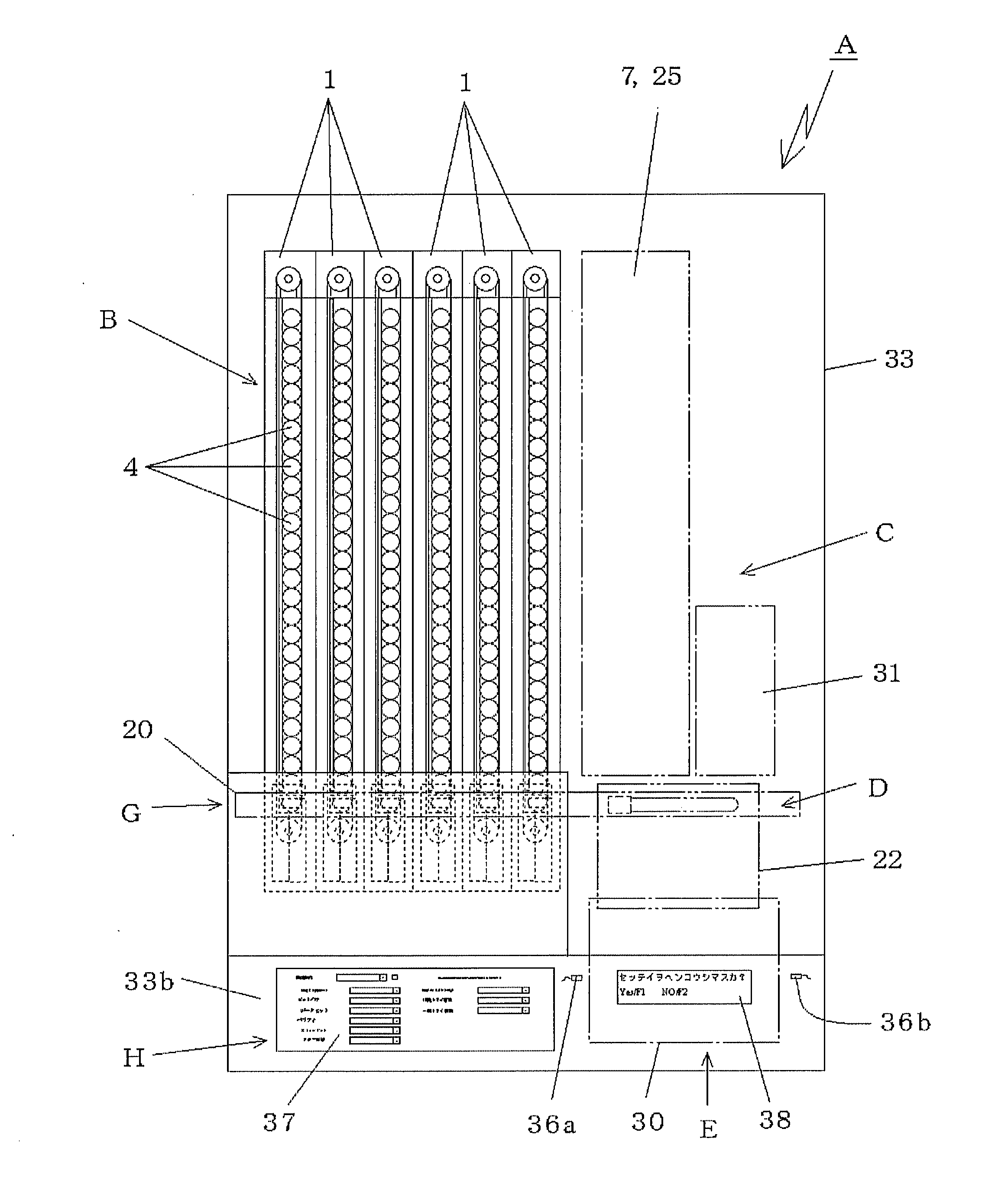
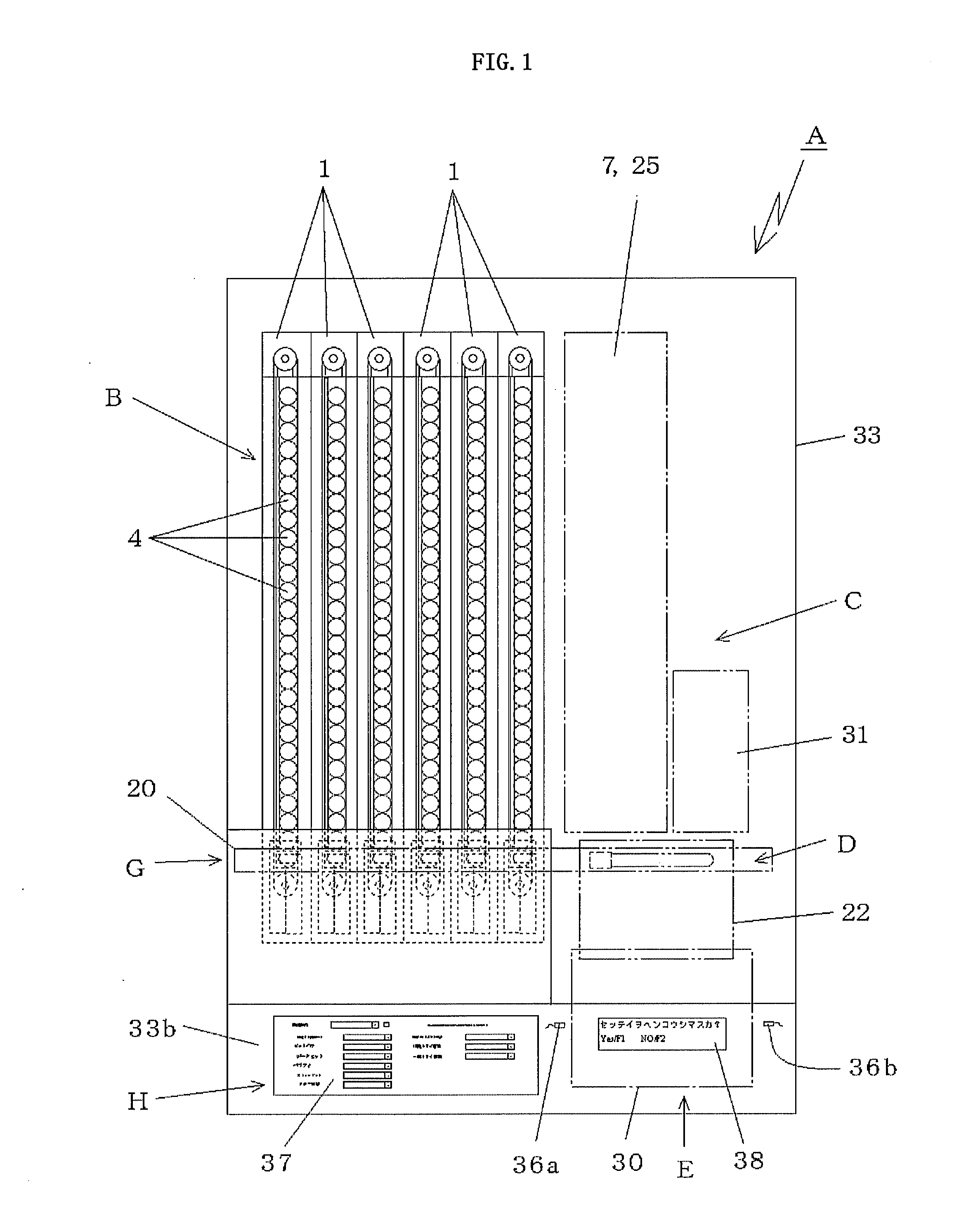
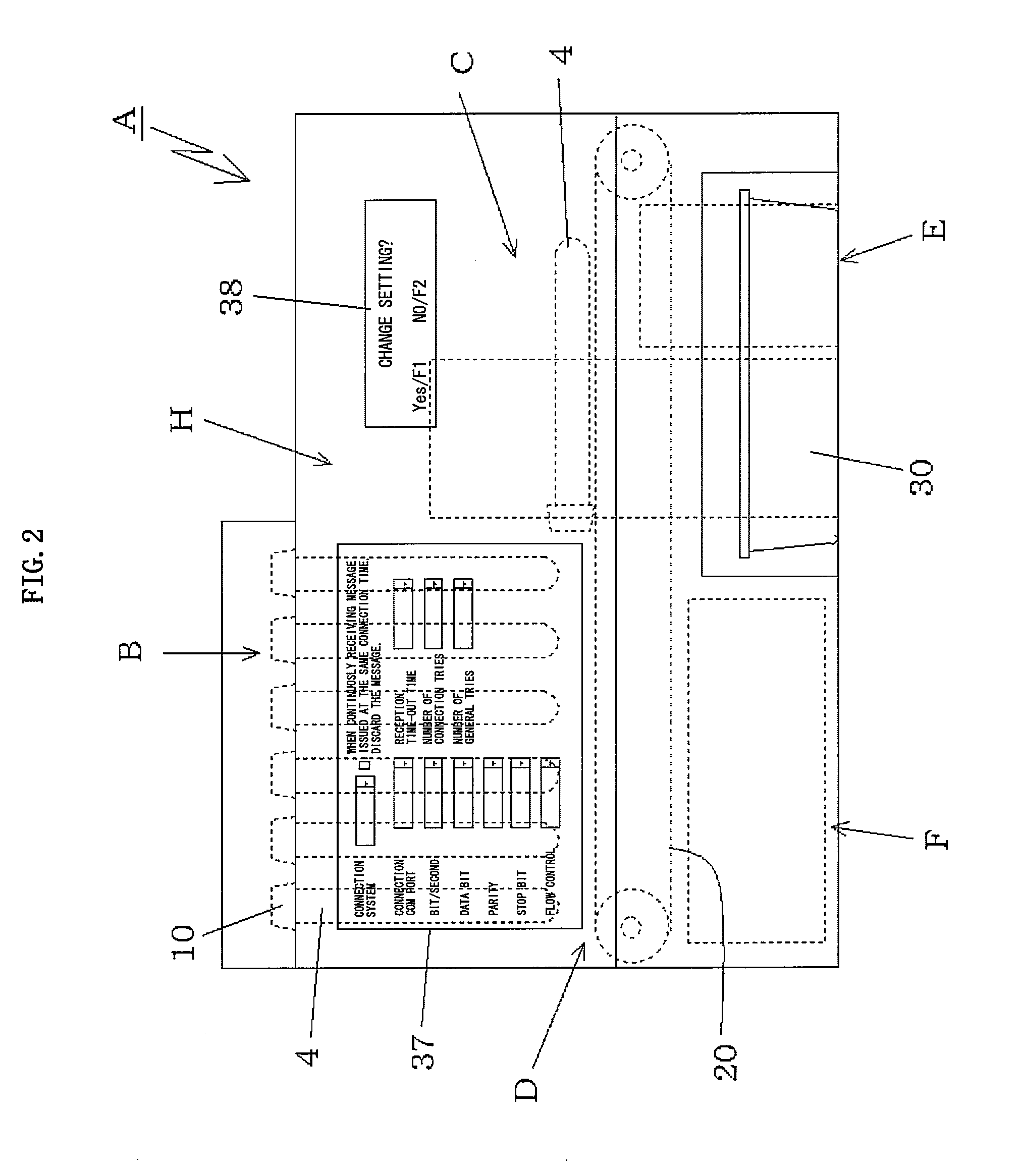
[0075]Hereinafter, a structure of the present invention is described as follows based on a first embodiment illustrated in FIGS. 1 to 10. First, a layout of equipment and mechanisms constituting a blood collection tube preparing apparatus A is described with reference to FIGS. 1 to 4. FIGS. 1 to 4 illustrate an entire structure of the blood collection tube preparing apparatus A. FIG. 1 is a plan view, FIG. 2 is a front view, FIG. 3 is a back view, and FIG. 4 is a left-hand side view. As illustrated in the plan view of FIG. 1, in the blood collection tube preparing apparatus A, a mounting portion B for a plurality of blood collection tube storage boxes 1 is provided to occupy almost a left half region. In this embodiment, six storage boxes 1 are placed in parallel with each other in the form of modules, and the modules of the blood collection tube storage boxes 1 are detachably mounted to the mounting portion on an apparatus main body 33 side. On a right side of the storage box mount...


PUM

PropertyMeasurementUnit
widthaaaaaaaaaa
outer diameteraaaaaaaaaa
diameteraaaaaaaaaa

Abstract

Provided is a blood collection tube preparing apparatus which is simple, downsized, portable, capable of being easily placed on a desk or the like, excellent in responding to an emergency such as a disaster, and capable of preparing various kinds of blood collection tubes depending on a blood collection instruction from a doctor. A blood collection tube holding member is arranged along one transferring belt and between a forward-side transferring belt and a backward-side transferring belt of the one transferring belt, and lower end surfaces of a cap of a blood collection tube is supported on upper end surfaces of the blood collection tube holding member and the forward-side transferring belt. The forward-side transferring belt applies a transferring force to the blood collection tube through the cap. Further, the members constituting a storage box are accommodated in one module, and the storage box is detachably mounted onto a mounting portion of an apparatus main body. Further, the storage box is in the form of module, and hence an operation in the case of failure or during maintenance is significantly facilitated.

Description

TECHNICAL FIELD[0001]The present invention relates to a blood collection tube storage box and a blood collection tube preparing apparatus which perform an operation of preparing a blood collection tube in advance in a blood collection step as a pre-step of a blood collection test. The blood collection tube preparing apparatus adopts, in a form of module, the blood collection tube storage box which is allowed to be easily attached and detached, and in which the blood collection tube (including a test tube) is held in a suspended manner within an endless transferring belt and the blood collection tube is transferred by the transferring belt. The blood collection tube preparing apparatus can select various kinds of blood collection tubes from the storage box in the form of module depending on a blood collection instruction from a doctor, stick a label on which blood collection information such as a patient ID and a content of the blood collection instruction is printed, and receive the...

Claims


Application Information

Patent Timeline
Patent Type & Authority Applications(United States)
IPC IPC(8): B65B1/04
CPCG01N35/04G01N2035/00326B65G35/02G01N2035/0406G01N2035/0484G01N2035/00861A61B5/15A61J3/00A61M1/02B65C3/14G01N35/00G01N2035/0091
Inventor YAMADA, TADAICHIRO
Owner AFC MINNESOTA
Learn More