Fuel pipe assembly and clamping means

a technology of clamping device and fuel pipe, which is applied in the direction of manufacturing tools, machines/engines, mechanical equipment, etc., can solve the problems of pipe failure, undesirable vibration and resonance (at engine vibration frequency), and pipe corrosion along the relatively long and flexible pipes, so as to reduce the radial clearance, enhance the clamping action, and reduce the axial distan

Active Publication Date: 2011-07-21
DELPHI TECH IP LTD
View PDF6 Cites 17 Cited by
  • Summary
  • Abstract
  • Description
  • Claims
  • Application Information

AI Technical Summary

Benefits of technology

[0019]In some embodiments, the proximal end of the tube nut is provided with an enlarged bore that is coaxially aligned with the through-bore of the tube nut. The enlarged bore is arranged to receive at least a portion of the locking nut. Conveniently, the attachment mechanism (or means) for engaging the locking nut with the tube nut comprises an internal (or female) screw-thread over at least part of the inner surface of the enlarged bore of the tube nut and a compatible external (or male) screw-thread provided over at least a portion of the outer surface of the locking nut. As previously indicated, the tube nut and locking nut are adapted such that when initially brought into contact with each other, for example, prior to engagement of their respective attachment means (e.g. screw-threads), a volume is defined therebetween, which is large enough to accommodate the clamp member or means in its unstrained (original) configuration. However, as the locking nut and tube nut are engaged with each other (e.g. by rotating the locking nut about the screw-thread), the axial distance (and hence the volume) between the two components reduces and the clamp member or means is compressed into a strained (deformed) configuration. Compression of the clamp member may continue until the tube nut and locking nut are fully engaged or until the components are suitably engaged and the compressed clamp member prevents closer association of the components. Compression of the clamp member may to some extent also reduce the radial clearance between the clamp member and the fuel pipe (relative to the clearance in the unstrained configuration), which may further enhance the clamping action on the sides of the fuel pipe. The compression of the clamp member between the locking nut and tube nut essentially prevents axial and lateral movement of the clamp member and, thus, of the fuel pipe.
[0020]In a beneficial embodiment the fuel pipe assembly is adapted to be received within a bore (e.g. a transverse bore) in the cylinder head. The transverse bore intersects with the injector pocket (or bore) provided in the cylinder head for receiving the fuel injector (or at least the injection nozzle). In this way, the head of the fuel pipe can be suitably located to engage the fuel injector within the cylinder. Suitably, the tube nut is provided with an attachment mechanism for engaging a compatible attachment mechanism of the cylinder head. Advantageously, the attachment mechanism for engaging the tube nut with the cylinder head comprises an external screw-thread over at least a portion of the outer surface of the proximal end of the tube nut, and a compatible internal screw-thread over at least a portion of the bore within which the tube nut is received. In use, correct engagement of the tube nut with the cylinder head generates a compressive force between the head (or distal end) of the fuel pipe and the associated seating surface of the injector, to create a substantially fluid tight seal between the fuel pipe and injector and prevent the leak of high pressure fuel between the interface. Suitably, the tube nut is provided with a thrust surface (at or towards its distal end) to exert an axial load onto the head of the fuel pipe in order to compress the end of the fuel pipe against the cooperating surface of the injector.
[0021]Typically, the distal end (or head) of the fuel pipe is provided with a male frusto-conical (or part-spherical) surface for cooperation with a female frusto-conical or part-spherical seating surface of the fuel injector. At least one part-spherical surface in the seating interface is advantageous to permit a degree of articulation between the fuel pipe and the injector at the interface of the cooperating surfaces. In this way, any inaccuracies in the machining of the fuel pipe and / or the injector may be compensated by the tolerance in the cooperation between the respective seating surfaces.

Problems solved by technology

On the other hand, engines that have this connection above the injector pocket (which is in the oil zone of the engine), may require a seal on the pipe at a position towards the outer end of the tube nut to eliminate “pockets” in which water and dust can be trapped, which might cause corrosion of the pipe and eventually lead to pipe failure.
In each of these prior art arrangements, the HP fuel pipe (and other components of the fuel supply line) can be adversely affected by engine vibrations, which can lead to undesirable vibrations and even resonance (at engine vibration frequencies) along the relatively long and flexible pipes.
Movement of the HP fuel pipes relative to the engine can cause repetitive stress of the pipes, particularly at the end regions, and this can lead to premature fatigue failure.
Such clamps add to the complexity and cost of the engine apparatus (e.g. by increasing the number of components necessary), and also increase engine crowding.

Method used


Image

  • Fuel pipe assembly and clamping means
  • Fuel pipe assembly and clamping means
  • Fuel pipe assembly and clamping means

Examples


Embodiment Construction

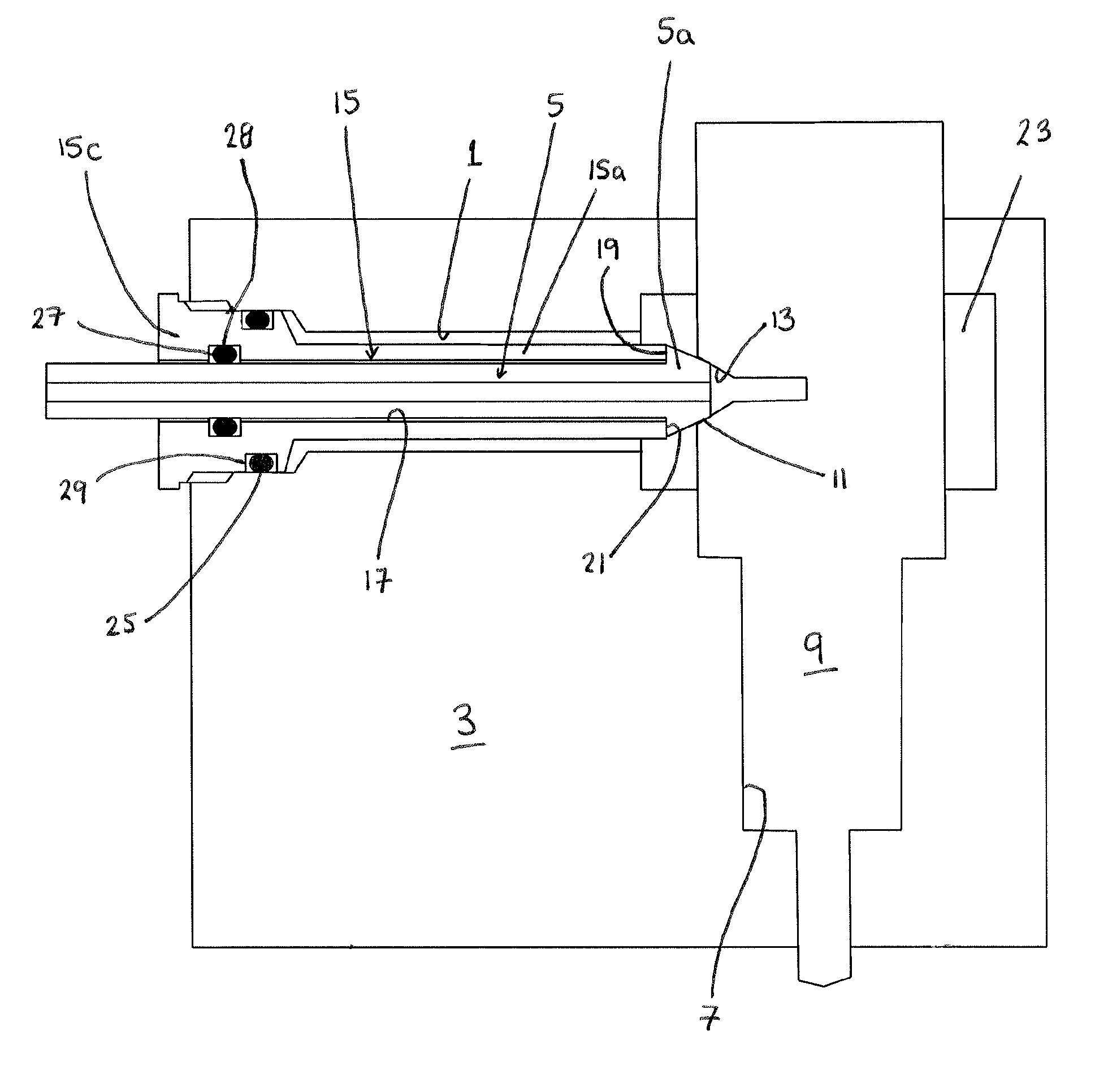
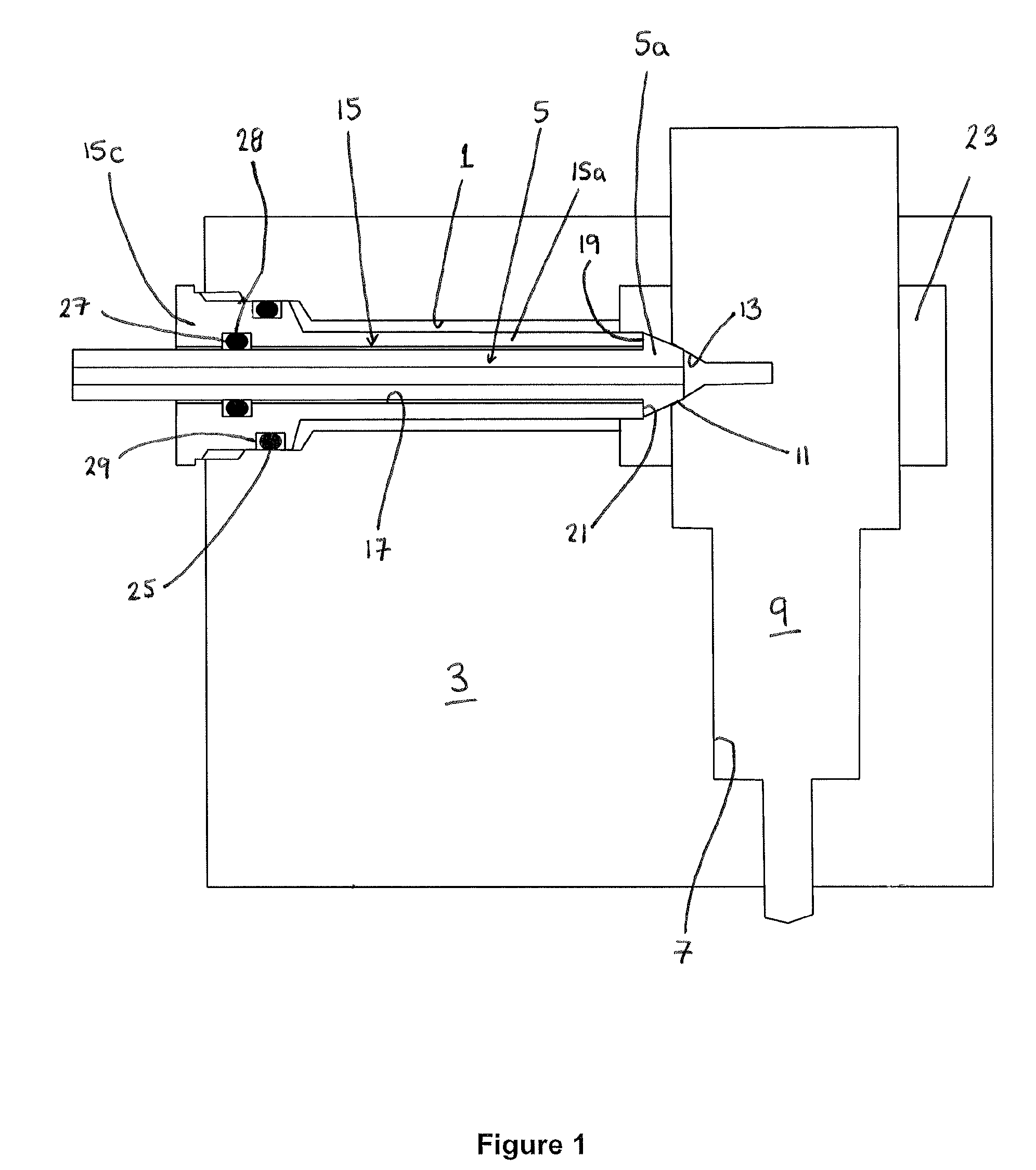
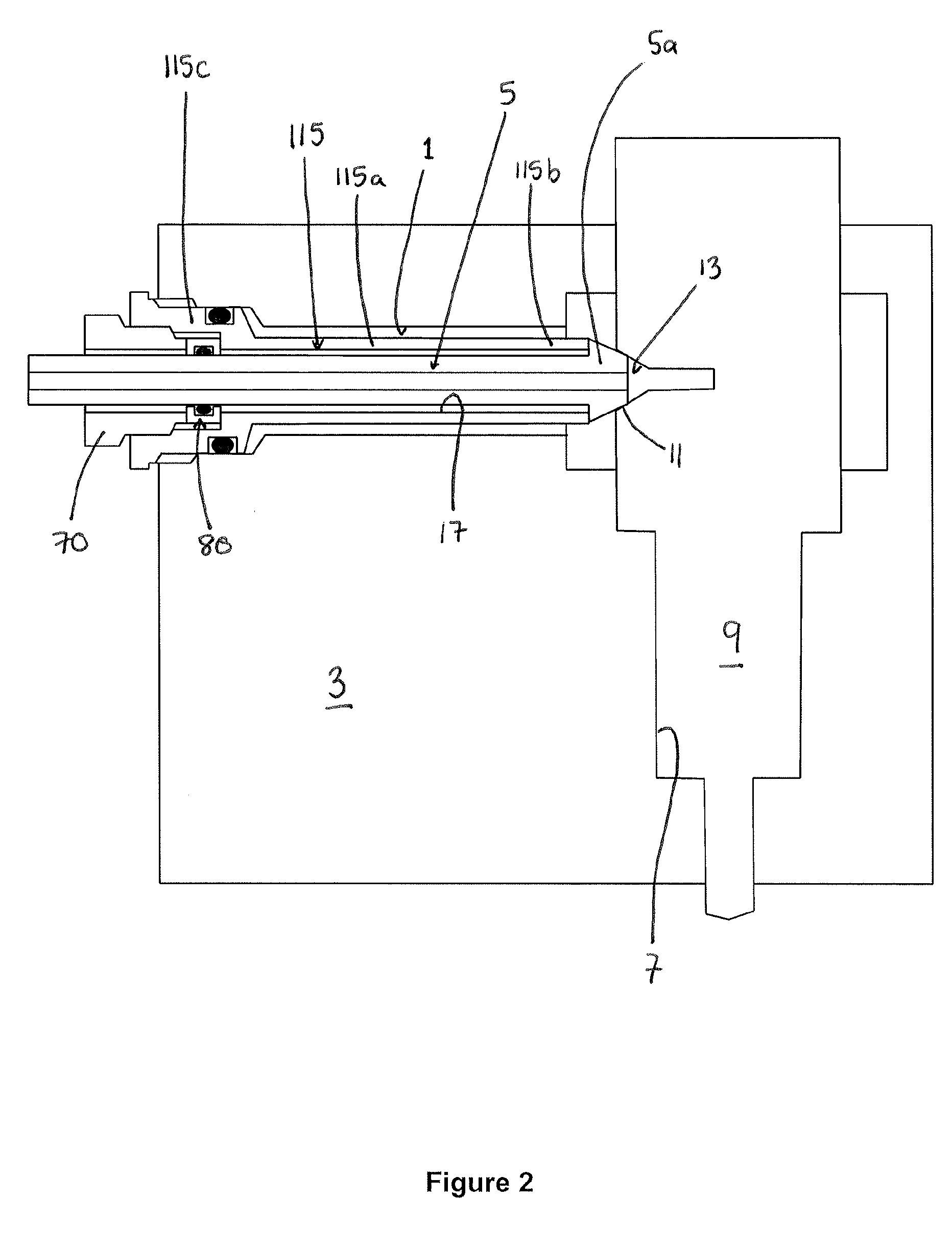
[0040]With reference to FIG. 1, in a prior art arrangement, a fuel pipe passage in the form of a transverse bore 1, within which a high pressure (HP) fuel pipe 5 is disposed, extends through cylinder head 3 to intersect with a bore (or “injector pocket”) 7 in which an injection nozzle 9 is housed. The distal end (or head) 5a of the fuel pipe 5 is provided with a male conical surface 11, which seals against a lateral seating face 13 on the body of the injection nozzle 9 when it is clamped in place by means of a tube nut 15. The tube nut 15 is adapted to be received within the bore 1 and has an elongate tubular region 15a at the injector (or distal) end and a radially enlarged region at its proximal end 15c to cooperate with an enlarged region of the transverse bore 1 at the outer surface of the cylinder head 3.

[0041]The tube nut 15 is provided with an axial through-bore 17 which receives the fuel pipe 5. The tube nut 15 has an axial length of substantially the length of the transvers...


PUM

PropertyMeasurementUnit
thicknessaaaaaaaaaa
diameteraaaaaaaaaa
pressureaaaaaaaaaa

Abstract

A fuel pipe assembly for supplying fuel to a fuel injector located within a bore of an engine cylinder head comprises a tube nut for connecting the fuel pipe to the fuel injector and a securing arrangement comprising a locking nut and a deformable clamp member for securing the fuel pipe within the tube nut. The tube nut comprises a tubular member defining an axial bore to receive the fuel pipe, a distal end shaped for cooperation with the head of the fuel pipe, and a proximal end having an attachment mechanism for engaging a compatible attachment mechanism of the locking nut. The locking nut has an axial bore to receive the fuel pipe, and an attachment mechanism for engaging a compatible attachment mechanism of the tube nut. The clamp member defines a bore to receive the fuel pipe and is deformable under compression. In a first state of engagement, the locking nut and tube nut define a volume therebetween that accommodates the clamp member in an unstrained configuration and the fuel pipe is able to move laterally. In a second state of engagement, the clamp member is compressed between the locking nut and tube nut into a strained configuration such that lateral movement of the fuel pipe is constrained.

Description

TECHNICAL FIELD[0001]This invention relates to a fuel pipe seal for use in a fuel line assembly that supplies fuel under high pressure to a fuel injector. In particular, the invention relates to a seal and clamping device for use in an arrangement of the type in which an injector is located within a bore provided in an engine cylinder head and fuel is supplied to the injector by a high pressure fuel pipe mounted to the cylinder head.BACKGROUND OF THE INVENTION[0002]In an internal combustion engine, it is known for a fuel pump to supply fuel at high pressure for delivery to each cylinder of the engine by means of a dedicated fuel injector. In a known arrangement, the fuel injector is received within a bore provided in a cylinder head of the cylinder (the “injector pocket”), and a high pressure (HP) fuel pipe (or fuel supply line) is used to provide a fluid connection between the fuel injector and the fuel pump or accumulator volume / common rail. Two such arrangements are known in the ...

Claims


Application Information

Patent Timeline
Patent Type & Authority Applications(United States)
IPC IPC(8): F02M55/00B23P11/00
CPCF02M55/005F02M55/02Y10T29/49895
Inventor MALE, ANDREW
Owner DELPHI TECH IP LTD
Why Eureka
Try Eureka