Method for gas-shielded arc brazing of steel sheet
a gas shielded arc and steel sheet technology, applied in the direction of welding/cutting media/materials, manufacturing tools, solvents, etc., can solve the problems of reducing the stability of the bead toe and the bead width, and affecting the production efficiency of the steel sheet. , to achieve the effect of reducing the generation of spatters, preventing excessive concentration of arcs, and reducing the voltage of ar
Inactive Publication Date: 2011-07-21
NIPPON SANSO CORP
View PDF14 Cites 42 Cited by
- Summary
- Abstract
- Description
- Claims
- Application Information
AI Technical Summary
Benefits of technology
[0052]According to the arc brazing method of the first aspect of the present invention, it is possible to prevent an unstable arc phenomenon thereby reducing the generation of spatters in not only low-speed arc brazing but also high-speed arc brazing. Also, it is possible to prevent excessive concentration of an arc and to reduce an arc voltage, and also to form beads having a uniform toe and to withstand gap of sheets and target-missing, thus making it possible to realize a reduction in generation of burn through and no gap bridging. It is also possible to rea
Problems solved by technology
An arc brazing method that has conventionally been used had a problem that protruding beads with a narrow bead width are likely to be formed because of poor wettability of beads, thus making it difficult to sufficiently ensure a contact surface between an upper sheet and a deposited metal.
However, when an argon gas inert to a shielding gas is used, oxygen forming the oxide is deficient and a cathode spot as a radiant spot of electrons is not stabilized, resulting in unstable generation of an arc thereby causing sputtering in which a molten metal scatters at the time of droplet transfer and also bead humping such as deterioration in stability of bead toe and bead width, and meandering bead.
Therefore, there was a defect in that an arc voltage is likely to increase and input heat increases, and burn through arises.
When the argon gas is used, wettability of beads becomes poor, and a narrow bead width is likely to be produced.
In the case of applying to joining of surface-treated steel sheets such as zinc coated steel sheets, wettability further deteriorates and humping beads are likely to be produced.
However, there was a problem that further destabilization of an arc and generation of spatters occur.
Therefore, it is difficult to increase brazing speed, and brazing is commonly executed in the range of less than 1.0 m/min.
However, droplet transfer is carried out only at the time of the generation of short circuit.
Therefore, when arc brazing using a CuAl type wire is carried out using this method, there is a problem that generated spatters are large as compared with a conventional droplet transfer method using pulse arc.
However, this method had a problem that behavior of an arc cannot be controlled and the generation of spatters caused by a phenomenon, wherein an arc is unstable, cannot be prevented.
However, this method had a problem that the generation of spatters caused by a phenomenon, wherein an arc is unstable, can be prevented but spatters caused by oxidation of beads cannot be prevented
Therefore, in case a pulse arc is carried out, a bead width decreases and thus stability of the bead toe deteriorates.
Therefore, allowance regarding a gap decreases and target missing tends to occur, thus making it difficult to realize speed-up.
Furthermore, since beads undergo severe oxidation by an oxidizing gas component in a shielding gas, golden beads, which is generally obtained by using a CuAl type wire, undergoes discoloration to a black color, and also wrinkles are generated on beads to cause problems in corrosion resistance and appearance.
As a result, it has been found that it is impossible to improve wettability of beads to a satisfactory level, although a phenomenon of an unstable arc is improved and thus a spatter generation amount decreases, as shown in Test Example described hereinafter.
Commonly, use of a shielding gas containing hydrogen
Method used
View moreImage
Smart ImageViewing Examples
Examples
 PUM
| Property | Measurement | Unit |
|---|---|---|
| Time | aaaaa | aaaaa |
| Thickness | aaaaa | aaaaa |
| Thickness | aaaaa | aaaaa |
Abstract
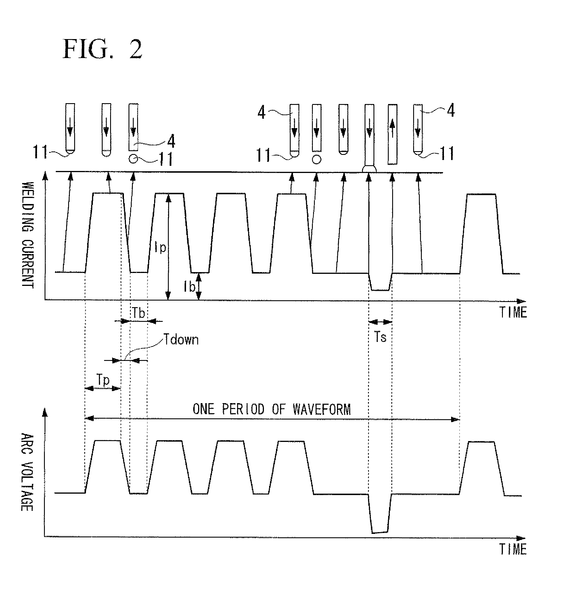
A method for gas-shielded arc brazing of a steel sheet; wherein a solid wire containing copper, as a main component, and aluminum is used in arc brazing of a steel sheet; and the method including periodically carrying out pulse droplet transfer and short circuit droplet transfer in arc brazing using, as a shielding gas, a mixed gas consisting of 0.03 to 0.3% by volume of oxygen gas and the remainder which is argon.
Description
TECHNICAL FIELD[0001]The present invention relates to a method of gas-shielded arc brazing of a steel sheet.[0002]This application claims priority on Japanese Patent Application No. 2008-252696 filed on Sep. 30, 2008 and Japanese Patent Application No. 2008-266722 filed on Oct. 15, 2008, the disclosure of which is incorporated by reference herein.BACKGROUND OF THE INVENTION[0003]Arc brazing is a brazing method using an electric arc as a heat source. It is a joining method in which a metal or alloy having a melting point lower than that of a base metal to be joined is used as a filler material and joining is carried out by scarcely melting a base metal, and is commonly executed using a welding source sold for arc welding.[0004]Arc brazing requires low heat input as compared with melt welding such as gas metal arc (GMA) welding. Accordingly, it generates less strain and enables joining of a joint with a large gap and is therefore suited for joining of thin sheets such as vehicle body ...
Claims
Login to View More Application Information
Patent Timeline
 IPC IPC(8): B23K9/16
CPCB23K1/14B23K3/063B23K9/02B23K9/09B23K9/173C21D2251/04B23K35/3046B23K35/38B23K35/383B23K2201/18B23K2203/04B23K35/0227B23K2101/18B23K2103/04
Inventor KAMEI, TOSHIKAZU
Owner NIPPON SANSO CORP
Features
- R&D
- Intellectual Property
- Life Sciences
- Materials
- Tech Scout
- Unparalleled Data Quality
- Higher Quality Content
- 60% Fewer Hallucinations
Learn More Browse by: Latest US Patents, China's latest patents, Technical Efficacy Thesaurus, Application Domain, Technology Topic, Popular Technical Reports.
© 2025 PatSnap. All rights reserved.Legal|Privacy policy|Modern Slavery Act Transparency Statement|Sitemap|About US| Contact US: help@patsnap.com


