Radiation detection element

a technology of detection element and radiation, applied in the direction of material analysis, radioation controlled devices, instruments, etc., can solve the problems of insufficient image quality and driving capability in the detection region, and achieve the effect of suppressing the variation of wiring load and increasing the arrangement pitch of connecting portions to connect with the external circui

Inactive Publication Date: 2011-07-21
FUJIFILM CORP
View PDF2 Cites 19 Cited by
  • Summary
  • Abstract
  • Description
  • Claims
  • Application Information

AI Technical Summary

Benefits of technology

[0022]According to the aspect of the present invention, the variation of the wiring load may be suppressed,

Problems solved by technology

Accordingly, when the variation of the wiring load of the scan lines and the signal lines i

Method used


Image

  • Radiation detection element
  • Radiation detection element
  • Radiation detection element

Examples


Embodiment Construction

[0030]Hereinafter, exemplary embodiments of the present invention will be described with reference to the drawings. A case in which the present invention is applied to a direct-conversion-type radiation detection element 10 that directly converts radiation into charges, will be described.

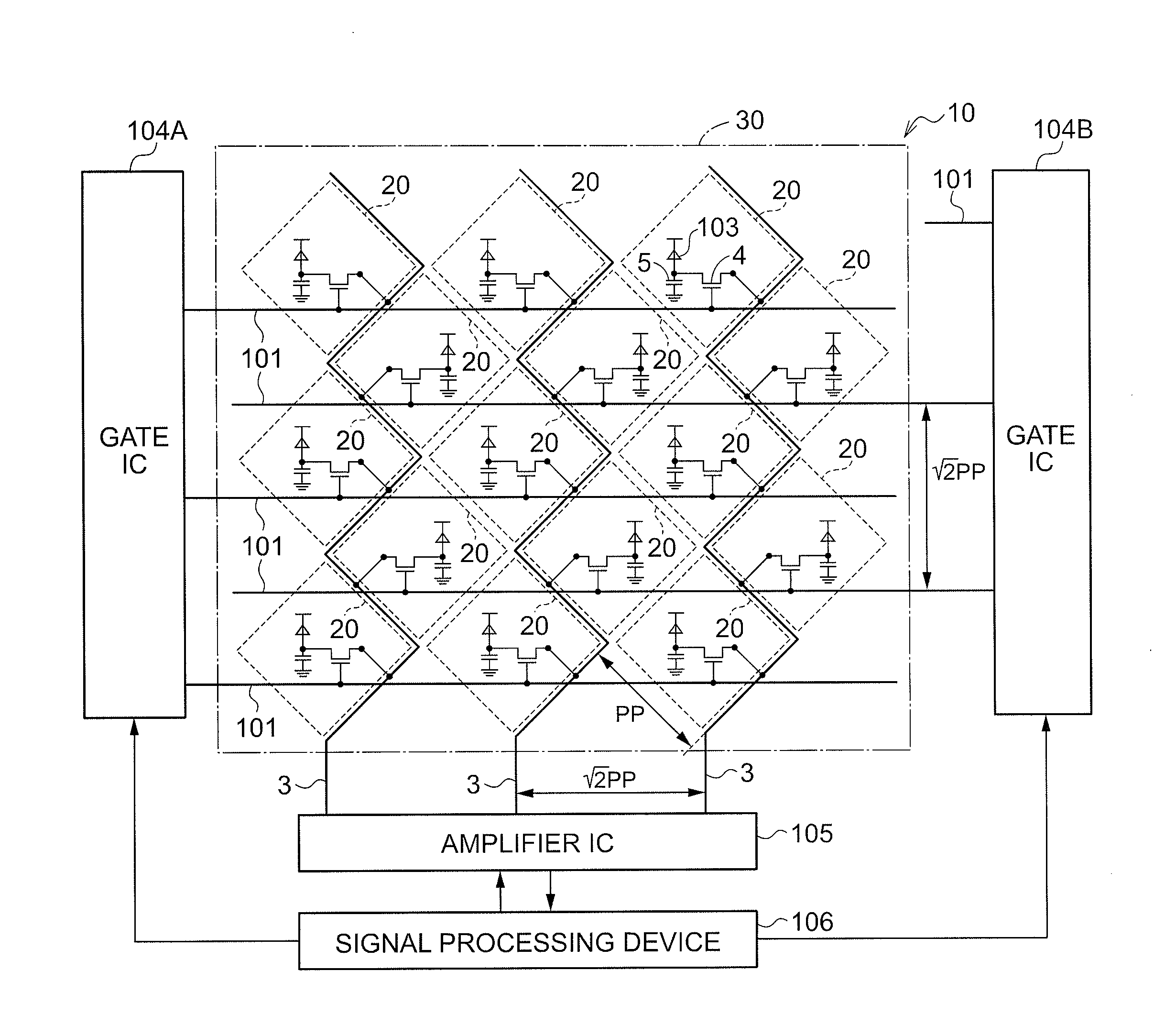
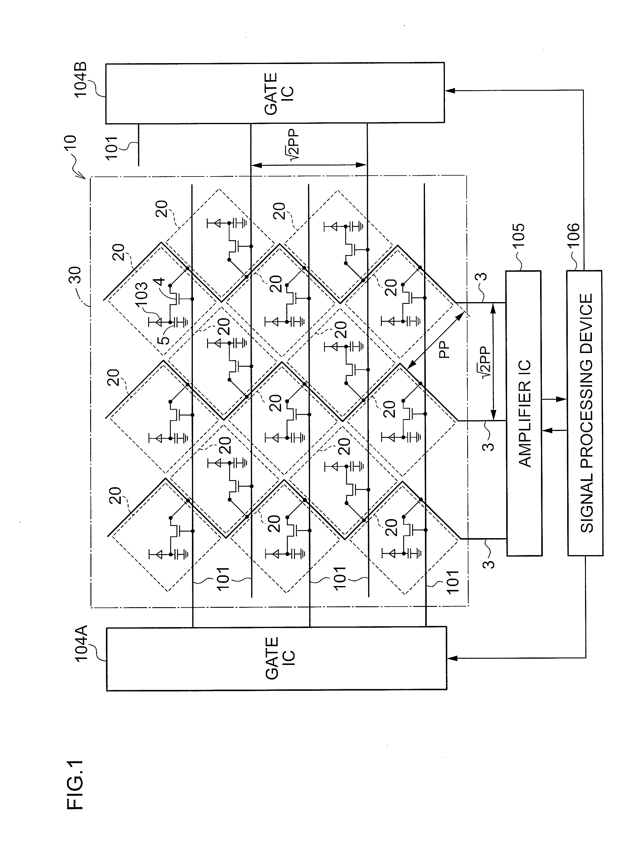
[0031]FIG. 1 shows the entire configuration of a radiographic imaging device 100 using a radiation detection element 10 according to the present exemplary embodiment.

[0032]As shown in FIG. 1, the radiographic imaging device 100 according to the present exemplary embodiment includes the radiation detection element 10 of the direct-conversion-type.

[0033]In the radiation detection element 10, a rectangular detection region 30 that has sides extending in first direction (horizontal direction of FIG. 1) and a second direction (vertical direction of FIG. 1) crossing first direction is provided. The radiation detection element 10 detects radiation that has been irradiated onto the detection region 30. In t...


PUM


Abstract

The present invention provides a radiation detection element that may suppress variation in wiring load, and that may increase the arrangement pitch of connecting portions connected to external circuits. Namely, plural pixels are disposed in an inclined matrix within a detection region, and a signal line is disposed for every two pixel lines in a vertical direction.

Description

CROSS-REFERENCE TO RELATED APPLICATION[0001]This application claims priority under 35 USC 119 from Japanese Patent Application No. 2010-007063, filed on Jan. 15, 2010 the disclosure of which is incorporated by reference herein.BACKGROUND OF THE INVENTION[0002]1. Field of the Invention[0003]The present invention relates to a radiation detection element. In particular, the present invention relates to a radiation detection element having plural pixels that are disposed in a matrix in a rectangular detection region, that accumulate charges generated by irradiation of radiation, and that includes switching elements to read out the accumulated charges.[0004]2. Description of the Related Art[0005]Recently, radiographic imaging devices using a radiation detection element, have been put into practice employing a radiographic imaging element of a FPD (flat panel detector), or the like. Such radiographic imaging elements have an X-ray sensitive layer disposed on a TFT (Thin Film Transistor) a...

Claims


Application Information

Patent Timeline
IPC IPC(8): H01L27/146
CPCH01L27/14603H01L27/14632H01L27/14658H01L27/14609H01L27/14659
Inventor OKADA, YOSHIHIRO
Owner FUJIFILM CORP
Why Eureka
Try Eureka