Picture coding apparatus, picture coding method, and recording medium having picture coding program recorded thereon

a picture coding and picture technology, applied in the field of picture coding apparatus, picture coding method, and recording medium having picture coding program recorded thereon, can solve the problems of variation in complexity, deterioration of picture quality of coded pictures, and conventional picture coding apparatus not controlling coding mode (or picture type) and the size of gop

Inactive Publication Date: 2005-06-14
MITSUBISHI ELECTRIC CORP
View PDF9 Cites 13 Cited by
  • Summary
  • Abstract
  • Description
  • Claims
  • Application Information

AI Technical Summary

Benefits of technology

[0028]The present invention is accomplished to eliminate the aforementioned drawbacks of the conventional picture coding apparatuses.
[0029]Accordingly, an object of the present invention is to realize high quality coding without failure of control of coding operations even in the case of coding instantaneously varying scenes and rapidly moving pictures.
[0030]Further, another object of the present invention is to realize highly efficient coding, by which the characteristics of a to-be-coded picture can be evaluated from different aspects according to long-term variation of complexity of the picture and the presence or absence of a scene change and by which variation in the coding quality can be suppressed within a restricted range of amounts of codes.
[0035]Furthermore, the group structure determining means may set a default value of the number of frames when the group is constituted. Moreover, when there is a part having low interframe correlation, the group structure determining means may set the number of frames of the group so that the boundary of the group is located in the part having low interframe correlation. Further, when the number of consecutive picture frames each having high interframe correlation exceeds the default value, the group structure determining means may set the number of frames of the group at a value that is larger than the default value.

Problems solved by technology

That is, in the case of coding instantaneously varying scenes and rapidly moving pictures, the feedback control often cannot follow the actual variation in the generated code amount and thus fails, with the result that the picture quality of coded pictures is deteriorated.
However, such a conventional control method is used for controlling mainly the quantization characteristics, so that change of coded picture quality is often visible on the change point of quantization characteristics.
Furthermore, the conventional picture coding apparatus does not control the coding mode (or picture type) and the size of GOP according to the characteristics of a picture to be coded, which are estimated from different aspects, for instance, the long-term variation in complexity of the picture, and the presence or absence of a scene change.
It is, thus, difficult to achieve highly efficient coding by suppressing the variation in the coding quality within a restricted range of amounts of codes.
However, in this case, the conventional apparatus has drawbacks in a very large amount of operation and a very large circuit size.

Method used


Image

  • Picture coding apparatus, picture coding method, and recording medium having picture coding program recorded thereon
  • Picture coding apparatus, picture coding method, and recording medium having picture coding program recorded thereon
  • Picture coding apparatus, picture coding method, and recording medium having picture coding program recorded thereon

Examples


first embodiment

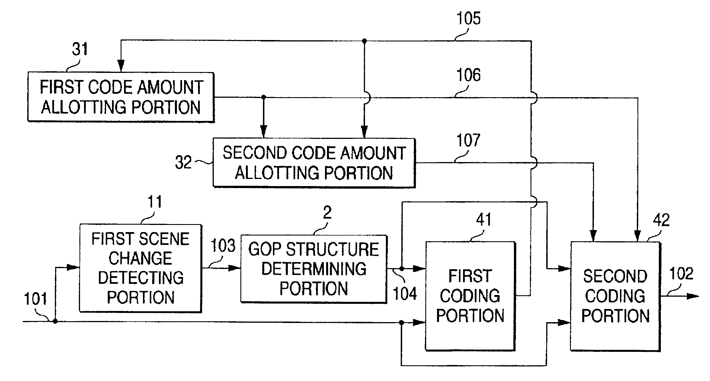
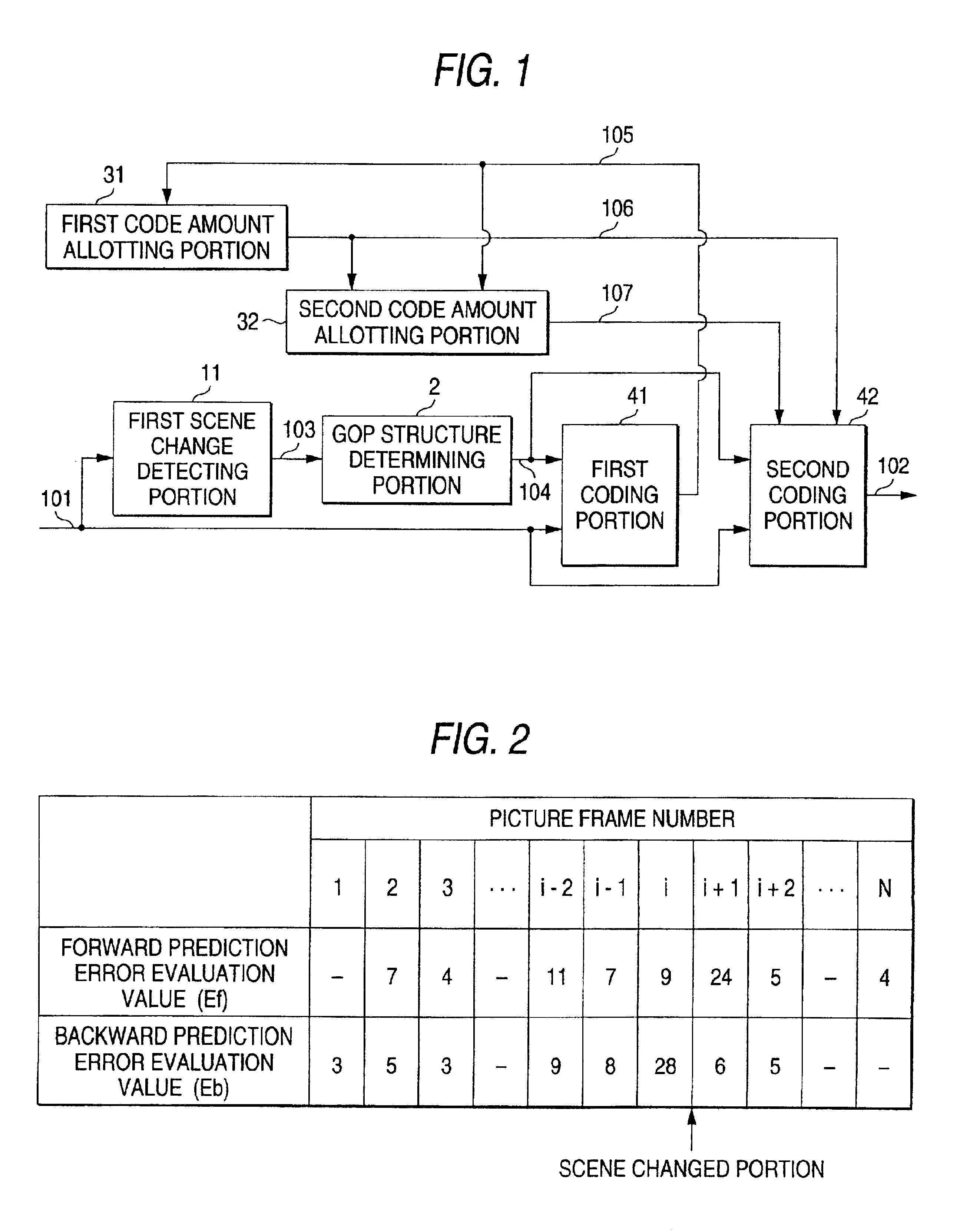
[0056]FIG. 1 is a block diagram illustrating a picture coding apparatus that is an embodiment of the present invention. In FIG. 1, reference numeral 11 designates a first scene change detecting portion serving as the scene change detecting means, 2 denotes a GOP structure detecting portion acting as the group structure determining means, 31 and 32 designate first and second code amount allotting portions serving as the code amount allotting means, 41 denotes a first coding portion serving as the preceding means, and 42 designates a second coding portion serving as the coding means.

[0057]In this embodiment, the correlation between picture frames corresponding to an input picture is evaluated. Then, a picture boundary having low interframe correlation is detected as a transition between scenes, namely, a scene change position. The constitution of a GOP is determined according to a result of this detection of a scene change and to the correlation between the picture frames. Moreover, t...

second embodiment

[0128]FIG. 7 is a block diagram illustrating the configuration of another picture coding apparatus according to the present invention. In FIG. 7, reference numeral 43 designates a third coding portion. The rest of the constituent elements of the apparatus are the same as the corresponding elements illustrated in FIG. 1. The third coding portion 43 is a common coding device serving as both the encoder used for preceding and the encoder used for coding. Incidentally, the third coding portion 43 uses a coding parameter used for preceding, which differs from a coding parameter used for coding. That is, parameters respectively corresponding to the coding modes are preliminarily set. Thus, when performing the preceding, the portion 43 uses the preset parameter for preceding.

[0129]With such a configuration, the scale of the apparatus can be decreased. This embodiment is effective especially in the case that real-time processing is unnecessary.

[0130]FIG. 8 is a block diagram illustrating th...


PUM


Abstract

A plurality of picture frames is arranged as one group according to correlation between picture frames in a picture sequence. Then, a coding mode corresponding to each of the picture frames of the group is determined. Subsequently, preceding is performed according to the coding mode. Then, the coding of a picture is performed by controlling a coding parameter according to a result of the preceding and to the coding mode.

Description

BACKGROUND OF THE INVENTION[0001]1. Field of the Invention[0002]This invention relates to the improvement of efficiency of picture coding of images formed by MPEG-2 video signals, and to digital broadcast service, Internet video distribution, and package media production.[0003]2. Description of the Related Art[0004]FIG. 9 is a process block diagram illustrating a conventional picture coding apparatus disclosed in, for example, JP-A-9-93537 official gazette.[0005]In FIG. 9, reference numeral 81 designates a picture frame reordering process, 82 denotes a differencing process, 83 designates a discrete cosine transform (DCT) process, 84 denotes a quantization process, 85 designates an inverse quantization process, 86 denotes an inverse DCT (IDCT), 87 designates an addition process, 88 denotes a motion compensation process, 89 designates a variable length coding process, 90 denotes a buffering process, and 91 designates a coding control process.[0006]Next, processing to be performed at t...

Claims


Application Information

Patent Timeline
Patent Type & Authority Patents(United States)
IPC IPC(8): H04N7/36H04N7/26H04N7/50H04N19/50H04N19/112H04N19/114H04N19/126H04N19/146H04N19/177H04N19/179H04N19/196H04N19/423H04N19/61H04N19/625H04N19/85H04N19/87H04N19/91
CPCH04N19/503H04N19/159H04N19/172H04N19/15H04N19/115H04N19/177H04N19/114H04N19/124H04N19/14H04N19/142H04N19/61
Inventor MATSUZAKI, KAZUHIROKATO, YOSHIAKIMURAKAMI, TOKUMICHI
Owner MITSUBISHI ELECTRIC CORP
Why Eureka
Try Eureka