Distributed illumination system
- Summary
- Abstract
- Description
- Claims
- Application Information
AI Technical Summary
Benefits of technology
Problems solved by technology
Method used
Image
Examples
Embodiment Construction
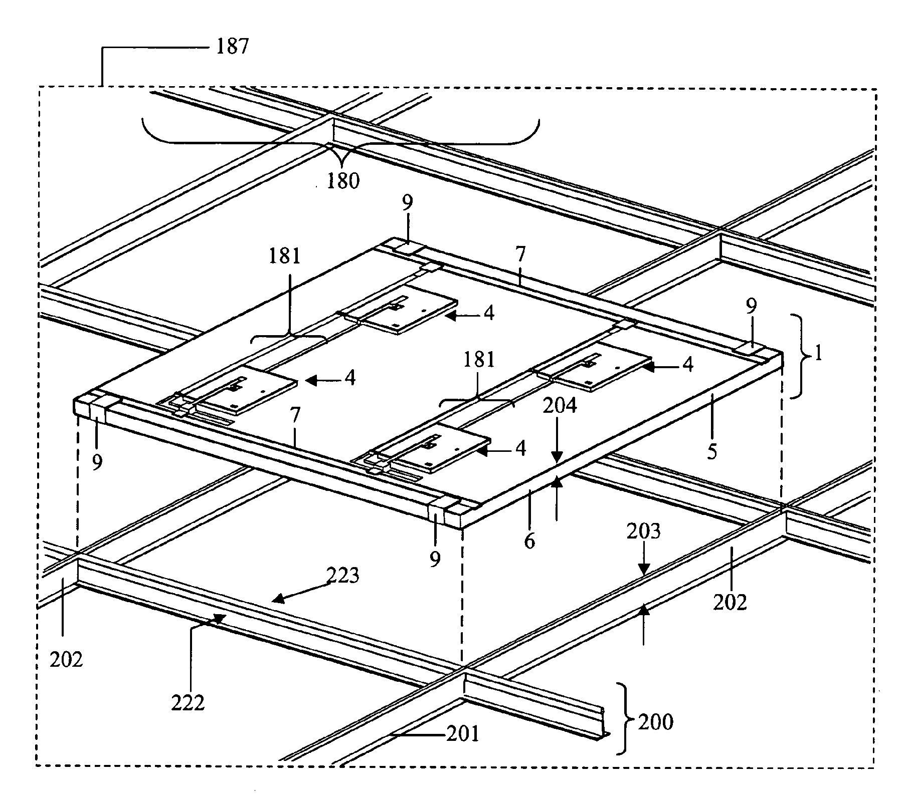
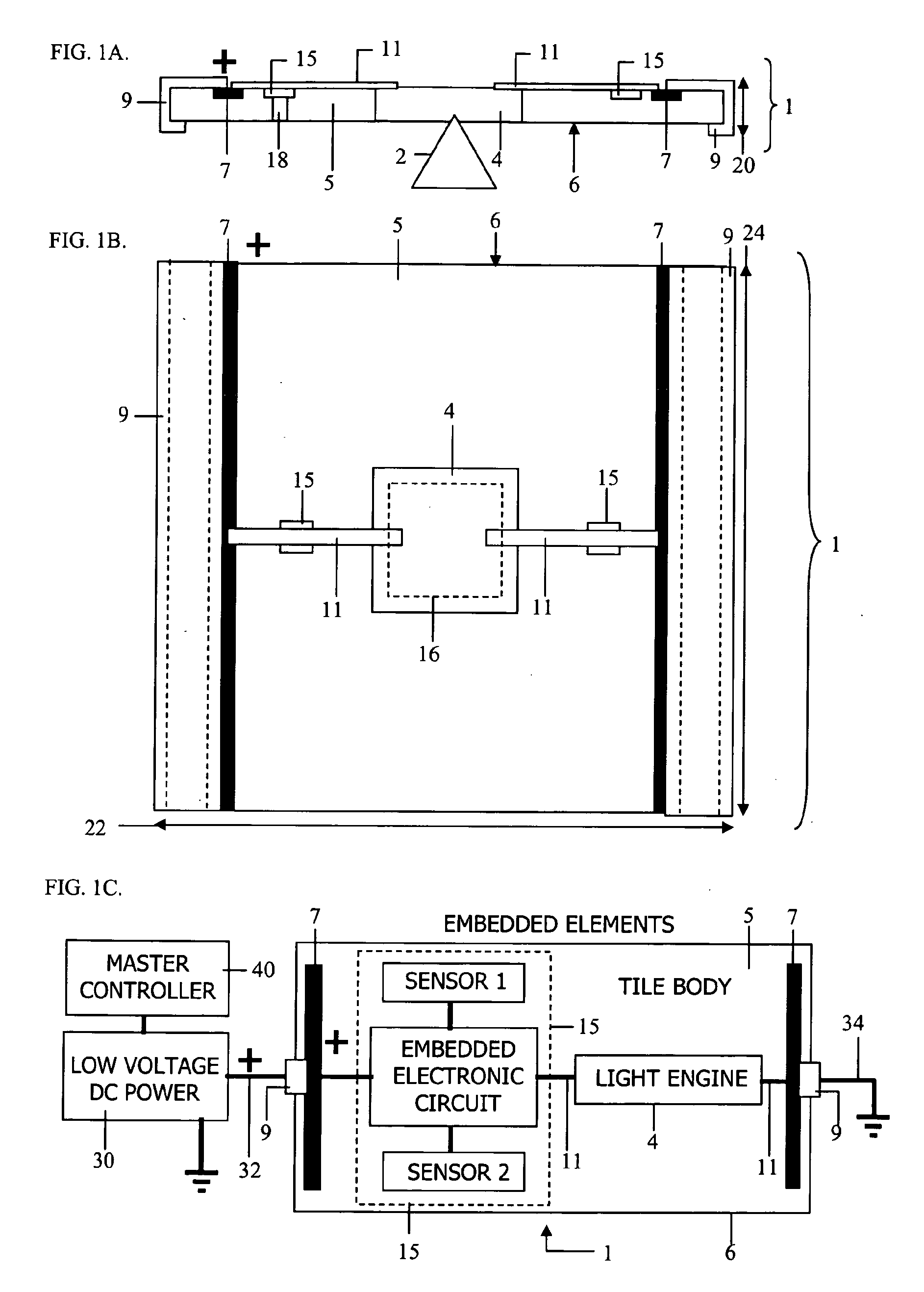
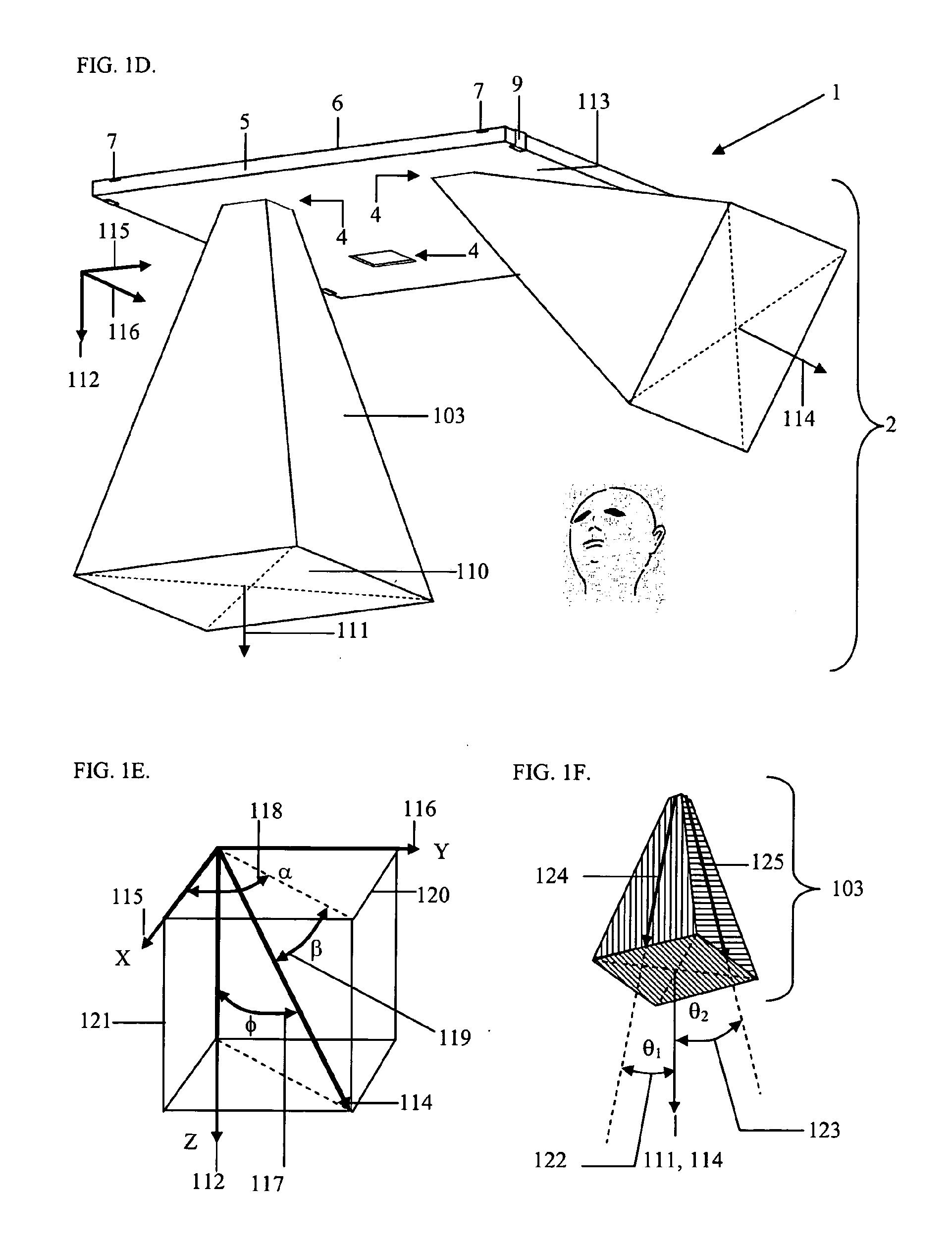
[0225]An optical system 1 constructed in accordance with the distributed overhead illumination system invention is shown in a generalized side view, FIG. 1A, in a generalized top view, FIG. 1B, and in a generalized block diagram form of electrical circuit schematic, FIG. 1C. For purposes of scaling, the cross-sectional thickness 20 of system 1 in FIG. 1A may be visualized as being 0.75 inches, and the edge boundaries 22 and 24 of system 1 in FIG. 1B may be visualized as being 2 feet by 2 feet square. In general, thickness 20 may vary between 0.25 inches and 1.5 inches, and edge boundaries 22 and 24 may vary between about 1-foot and about 6-feet, with the nominal dimensional combinations 2 feet by 2 feet and 2 feet by 4 feet being most popular among commercial standards. Within this description, all of the examples illustratively describe 24″×24″ panel materials, most often referred to a “tile.” In addition, all of the ceiling illumination examples provided below anticipate use in su...
PUM
 Abstract
Description
Claims
Application Information
 - R&D
- Intellectual Property
- Life Sciences
- Materials
- Tech Scout
- Unparalleled Data Quality
- Higher Quality Content
- 60% Fewer Hallucinations
Browse by: Latest US Patents, China's latest patents, Technical Efficacy Thesaurus, Application Domain, Technology Topic, Popular Technical Reports.
© 2025 PatSnap. All rights reserved.Legal|Privacy policy|Modern Slavery Act Transparency Statement|Sitemap|About US| Contact US: help@patsnap.com


