Motor magnetic-pole-position estimating apparatus

a technology of motor magnetic and estimating apparatus, which is applied in the direction of motor/generator/converter stopper, electronic commutator, dynamo-electric converter control, etc., can solve the problems of complex apparatus configuration, low rotation speed, and inability to calculate phase difference according to conventional techniques

Inactive Publication Date: 2011-07-21
HONDA MOTOR CO LTD
View PDF7 Cites 45 Cited by
  • Summary
  • Abstract
  • Description
  • Claims
  • Application Information

AI Technical Summary

Problems solved by technology

Unfortunately, the apparatus according to the conventional technique cannot calculate the phase difference at a low rotation speed including a situation in which the motor is stopped.
Ho

Method used


Image

  • Motor magnetic-pole-position estimating apparatus
  • Motor magnetic-pole-position estimating apparatus
  • Motor magnetic-pole-position estimating apparatus

Examples


Embodiment Construction

[0017]A motor magnetic-pole-position estimating apparatus according to an embodiment of the present invention will be described below with reference to the attached drawings, wherein like reference numerals designate corresponding or identical elements throughout the various drawings.

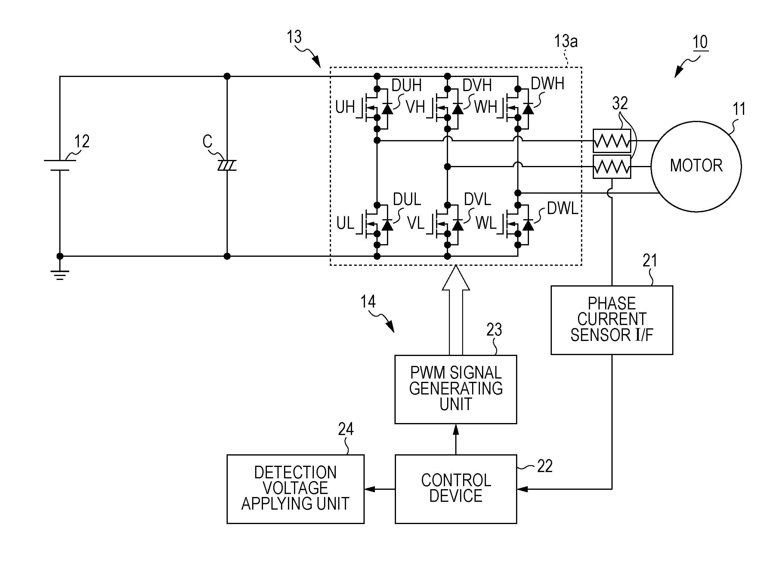
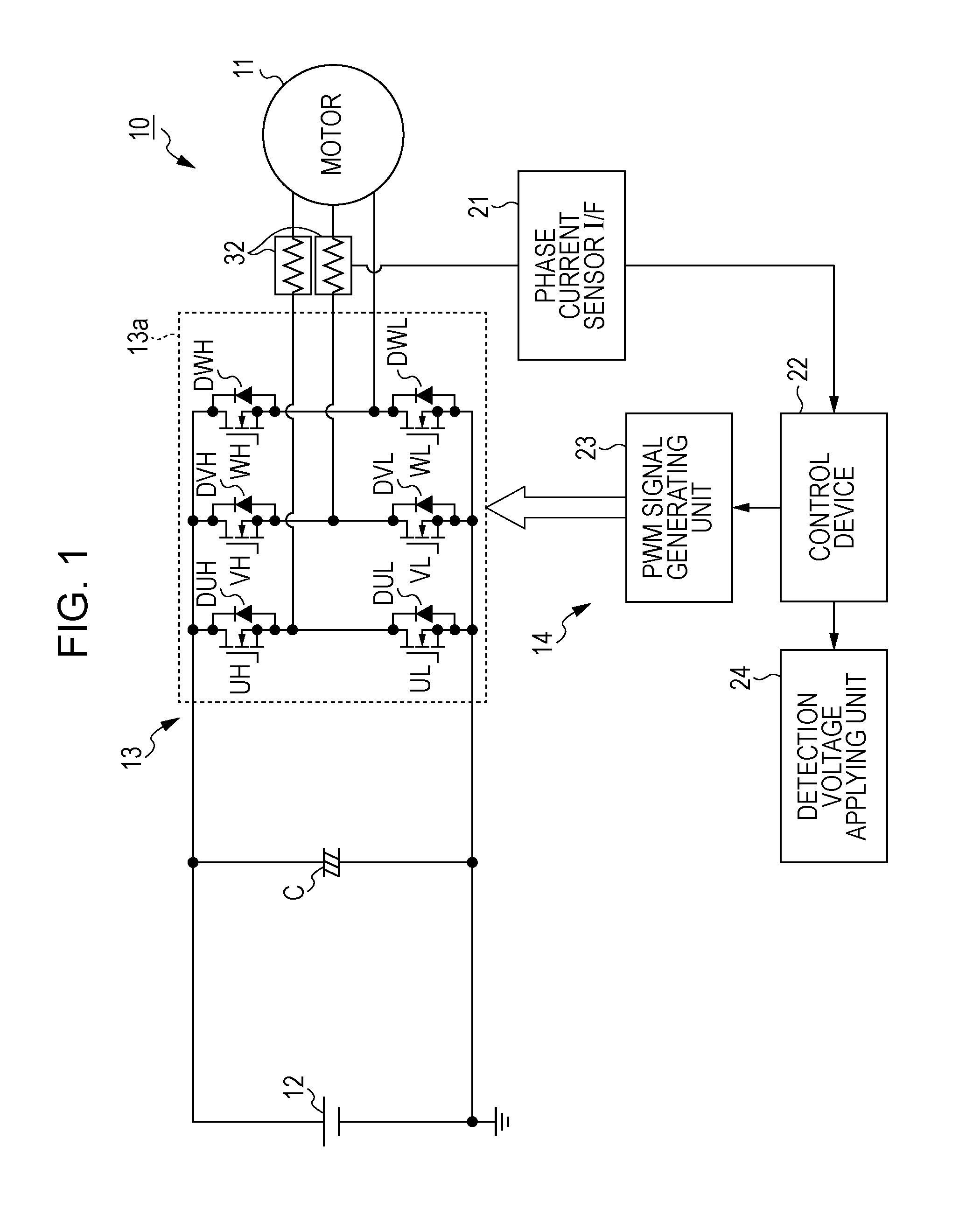
[0018]A motor magnetic-pole-position estimating apparatus 10 according to this embodiment (hereinafter, merely referred to as magnetic-pole-position estimating apparatus 10) estimates, for example, a magnetic-pole position (i.e., a rotation angle of a magnetic pole of a rotor from a predetermined reference rotation position) of a three-phase alternating-current brushless DC motor 11 (hereinafter, merely referred to as motor 11). The motor 11 includes a rotor (not shown) having a permanent magnet used as a field magnet of the motor 11, and a stator (not shown) that generates a rotation magnetic field for rotating the rotor. For example, the magnetic-pole-position estimating apparatus 10 includes an inver...


PUM


Abstract

A motor magnetic-pole-position estimating apparatus includes a command voltage output device and a current detector. A model-current calculator is configured to calculate a model current corresponding to a voltage equation for a predetermined model of a motor based on a command voltage and an actual current. A current-difference calculator is configured to calculate a current difference between the model current and the actual current. Each of first and second magnetic-pole-position-difference calculators is configured to calculate a magnetic-pole-position difference between an actual magnetic-pole position of the motor and an estimated or designated magnetic-pole position based on the current difference depending on whether or not a rotation speed of the motor is lower than a predetermined value. A magnetic-pole-position calculation device is configured to calculate the magnetic-pole position of the motor based on the magnetic-pole-position difference calculated by the first or second magnetic-pole-position-difference calculator.

Description

CROSS-REFERENCE TO RELATED APPLICATIONS[0001]The present application claims priority under 35 U.S.C. §119 to Japanese Patent Application No. 2010-007019, filed Jan. 15, 2010, entitled “MOTOR MAGNETIC-POLE-POSITION ESTIMATING APPARATUS”. The contents of this application are incorporated herein by reference in their entirety.BACKGROUND OF THE INVENTION[0002]1. Field of the Invention[0003]The present invention relates to a motor magnetic-pole-position estimating apparatus.[0004]2. Description of the Related Art[0005]A conventionally known apparatus for, for example, a synchronous motor having saliency is an apparatus that calculates a phase difference by using that an induced voltage changes in accordance with a phase, based on a voltage equation of control axes (dc-qc coordinate axes) having a phase difference with respect to dq coordinate axes of real axes, and calculates the phase of the control axes from the calculation result (for example, see Japanese Patent Laid-Open No. 2001-25...

Claims


Application Information

Patent Timeline
IPC IPC(8): H02P6/18H02P6/06H02P6/16H02P6/08H02P6/17H02P6/182H02P6/28H02P21/00H02P21/13H02P21/14H02P21/18H02P21/22H02P21/24H02P21/28H02P23/12H02P23/14H02P23/16H02P23/28H02P27/04H02P27/08
CPCH02P6/18H02P6/181H02P6/186H02P2203/05H02P21/0042H02P21/146H02P2203/01H02P6/188H02P21/18H02P21/26
Inventor AKIYAMA, MASAHIKO
Owner HONDA MOTOR CO LTD
Why Eureka
Try Eureka