Optical Coherence Tomography Methods and Systems

a coherence tomography and optical coherence technology, applied in the field of optical coherence tomography (oct) systems and methods, can solve the problems of sensitivity or the requirement of the total intensity of the measurement light illuminating the object, and the components are expensive and complex, and achieve the effect of reducing the sensitivity or the requirement of the total intensity of the measurement ligh

Active Publication Date: 2011-07-21
CARL ZEISS MEDITEC AG
View PDF14 Cites 24 Cited by
  • Summary
  • Abstract
  • Description
  • Claims
  • Application Information

AI Technical Summary

Benefits of technology

[0033]According to an embodiment of the present invention, the respective illuminating the object region comprises scanning an illumination beam of measuring light across the object region, the illumination beam having a beam waist located at an average depth of the object region such that a Rayleigh range of the illumination beam substantially corresponds to an axial field of view of the OCT method. A beam waist is a minimal lateral extension of a measuring light beam bundle, which is preferably located at the object region. The lateral extension of the measuring light beam bundle will increase to the square root of 2 times the waist a distance of half the Rayleigh range away from the location of the waist along a direction of propagation of the measuring light. Via the scanning it is possible to acquire not only structural data across a depth direction at a single lateral point of the object region, but to acquire structural data along a depth direction of the object at plural different lateral positions of the object to acquire structural data of a volume portion defined by a lateral scanning range and an axial field of view during the first measurement and an axial field of view during the second measurement, respectively. Further, by this provision the lateral resolution of the acquired structural data does not significantly change across the depth direction.
[0038]The controller is adapted to adjust the adjustable spectral width and to adjust the adjustable dispersion of the spectrometer based on an input signal. The input signal may be directly or indirectly supplied by a user or any other component of the system. The adjusting the adjustable spectral width and the adjustable dispersion of the spectrometer may occur in mutual dependency, i.e. the adjustable dispersion of the spectrometer may be adjusted based on at least a set spectral width or the adjustable spectral width may be adjusted based on at least a set dispersion of the spectrometer. The provided system allows acquisition of structural data along a depth direction of an object having adjustable axial resolution and adjustable axial field of view. Further, a spectral width of the spectrum of the measuring light illuminating the object may be a minimal spectral width required to achieve a predetermined axial resolution of structural data of the object.
[0041]According to an embodiment of the present invention, the controller is adapted to adjust the spectral width and the dispersion of the spectrometer such that a width of an overlap between a wavelength range of the dispersed superimposed light incident onto the positionally resolving detector and the adjusted spectral width amounts to at least 70%, in particular to at least 90% of the adjusted spectral width. Thus, it is possible to illuminate the object with measuring light merely comprising wavelengths that are detected in the superimposed light. Thereby, a total power of measuring light illuminating the object can be reduced to a minimum required to obtain structural information about the object having a given axial resolution. This enables to investigate in particular sensitive biological objects such as a human eye using the inventive system.
[0044]According to an embodiment of the present invention, the spectrometer comprises an imaging optics arranged in the beam path of the superimposed light upstream of the positionally resolving detector. The imaging optics advantageously allows collecting the superimposed and potentially dispersed light onto the positionally resolving detector, to improve a sensitivity and efficiency of the system. The imaging optics may comprise refractive optical elements such as lenses which may have spherical or aspherical surfaces and may also comprise optical refractive elements having different refractive powers in two different directions perpendicular to an optical axis, such as cylinder lenses.
[0055]According to an embodiment of the present invention a maximum of a difference between the peak wavelength of the first measuring light and the peak wavelength of the second measuring light is in the first measurement at least 2 times, in particular 5 times, greater than in the second measurement. Thereby, the resolution of the obtained structural data may be higher in the first measurement than in the second measurement, while concurrently the axial field of view is smaller in the first measurement than in the second measurement. Thus, a zoom effect is achieved.
[0064]According to an embodiment of the present invention, the illumination system is adapted such that the measuring light filtered using the first sweepable spectral filter has a spectral distribution having a first spectral width, the measuring light filtered using the second sweepable spectral filter has a spectral distribution having a second spectral width, wherein the first spectral width is at least two times, in particular at least five times, greater than the second spectral width. The spectral width of the measuring light illuminating the object region, returned from the object region, superimposed with reference light, and detected by the detector affects an axial depth of view of structural information obtained from the object along a depth direction. Thus, the present embodiment enables acquisition of structural data of an object along a first axial depth of view and along a second depth of view, wherein the first depth of view is smaller than the second depth of view. Further, an axial resolution may be selected differently in the two cases by choosing two different sweeping ranges of the measuring light illuminating the object region. Thus, a zoomable OCT system is provided providing enormous advantages in examining biological objects such as a human eye, in particular during surgery.

Problems solved by technology

However, the conventional OCT systems either require expensive components, elaborate adjustments of components, or exhibit disadvantages regarding sensitivity or a required total intensity of measuring light illuminating the object.

Method used


Image

  • Optical Coherence Tomography Methods and Systems
  • Optical Coherence Tomography Methods and Systems
  • Optical Coherence Tomography Methods and Systems

Examples


Embodiment Construction

[0072]In the exemplary embodiments described below, components that are alike in function and structure are designated as far as possible by alike reference numerals. Therefore, to understand the features of the individual components of a specific embodiment, the descriptions of other embodiments and of the summary of the invention should be referred to.

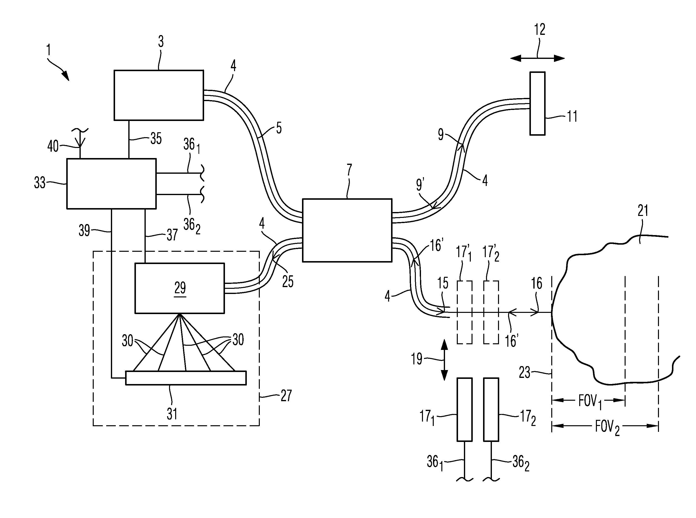
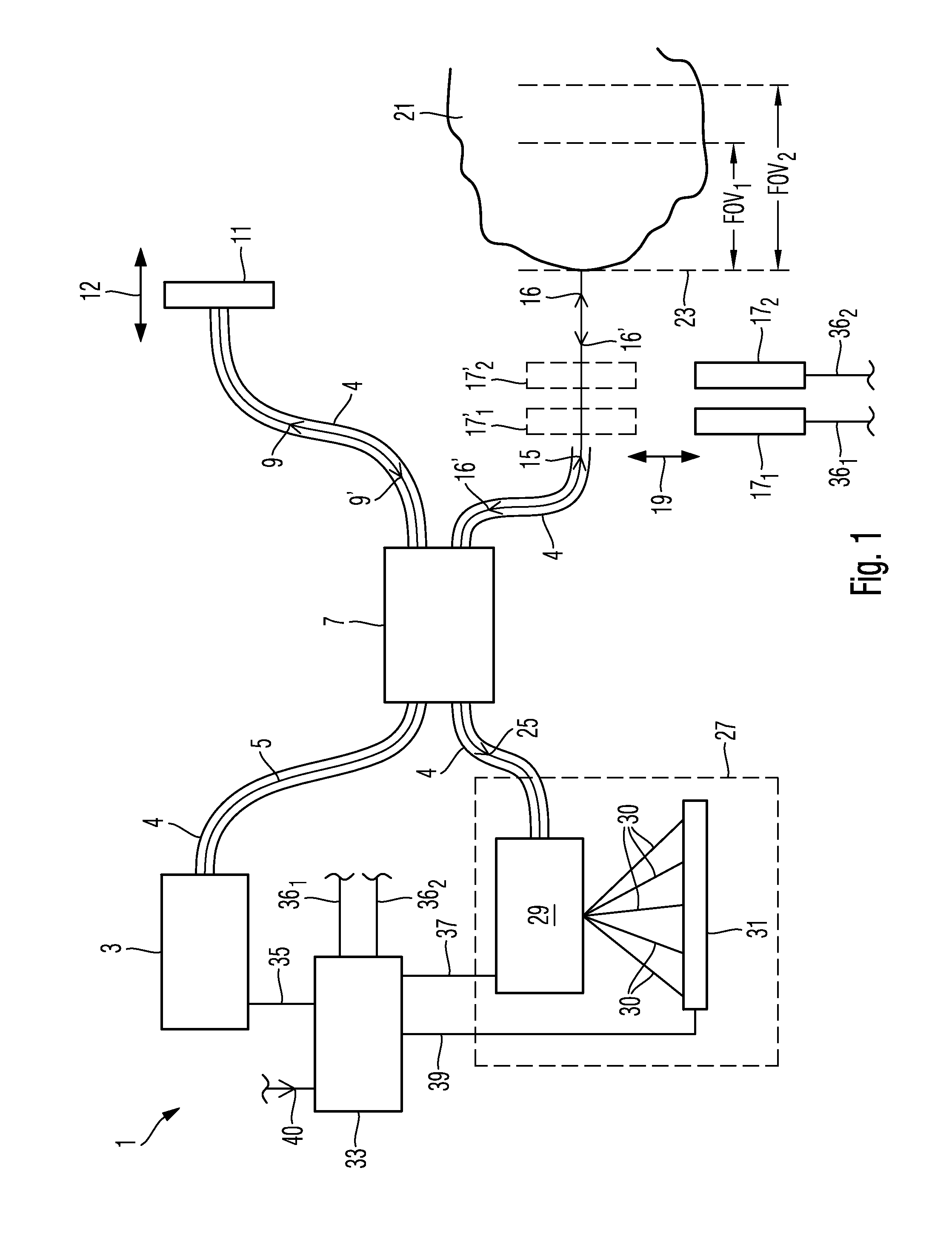
[0073]FIG. 1 schematically illustrates a spectral domain OCT system 1 according to an embodiment of the present invention.

[0074]OCT system 1 comprises a light source 3 configured to generate light 5 distributed according to a particular spectrum. There are two variants of this embodiment described below.

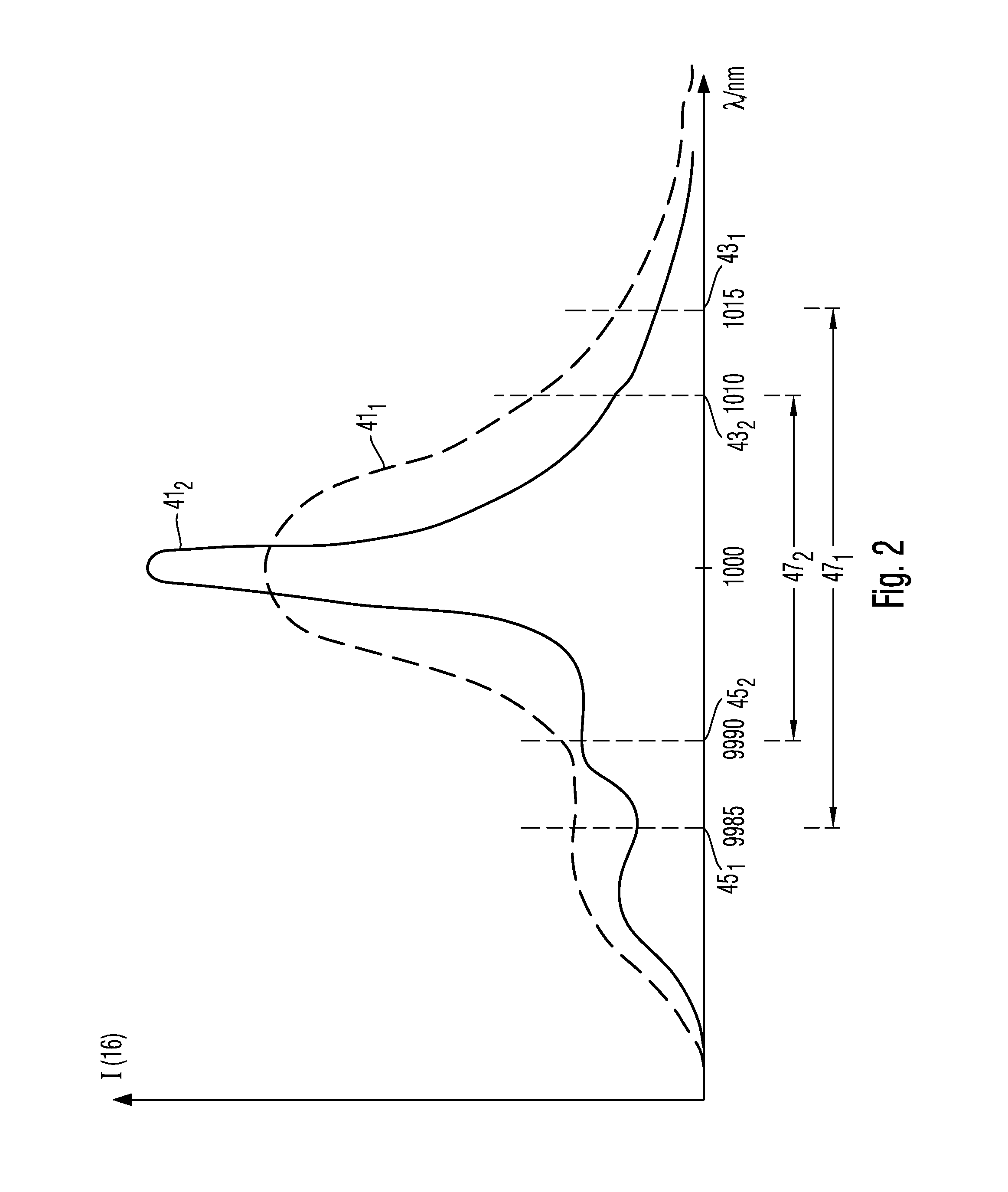
[0075]In a first variant of the OCT system 1 light source 3 comprises a super-luminescent diode adapted to generate light 5 having a spectrum with a mean wavelength of around 1000 nm and having an adjustable spectral width. The spectral width is adjusted by adjusting an electric current supplied to the super-luminescent diode (SLD). D...


PUM


Abstract

Frequency domain optical coherence tomography (FD-OCT) systems and methods are provided. Thereby, a first measurement and a second measurement is performed, wherein in the first measurement an object region is illuminated by measuring light having a spectrum with a first spectral width and in the second measurement the object region is illuminated with measuring light having a spectrum with a second spectral width, wherein the first spectral width is at least 10% greater than the second spectral width. Further, during the first measurement intensities of spectral ranges of light having interacted with the object and being superimposed with reference light are detected, wherein a width of these spectral ranges is greater than a corresponding width during the second measurement. Thus, switching an axial field of view of structural information of the object across a depth direction is enabled upon minimizing radiation damage at the object.

Description

CROSS-REFERENCES TO RELATED APPLICATIONS[0001]The present application claims priority to and is a continuation of International Patent Application No. PCT / EP2009 / 005152, filed on Jul. 15, 2009 and claims benefit under 35 U.S.C. §119(e) of U.S. Provisional Patent Application No. 61 / 081,343, filed on Jul. 16, 2008, the disclosures of which are hereby incorporated by reference in their entirety for all purposes.BACKGROUND OF THE INVENTION[0002]The present invention relates to optical coherence tomography (OCT) systems and methods. In particular, the present invention relates to frequency domain optical coherence tomography (FD-OCT) systems and methods. In particular, the present invention relates to FD-OCT systems and methods capable of adjusting an axial field of view of structural data acquired from an object.[0003]Optical coherence tomography (OCT) is an optical interferometric method for gaining structural information about an object. For this, the object is illuminated with measur...

Claims


Application Information

Patent Timeline
Patent Type & Authority Applications(United States)
IPC IPC(8): G01B9/02
CPCA61B3/102A61B3/1225A61B5/0066A61B5/0073G01B9/02091G01B9/02004G01B9/02007G01B9/02044G01N21/4795G01B9/02009
Inventor HACKER, MARTINHAUGER, CHRISTOPHO'HARA, KEITHMEYER, SCOTT
Owner CARL ZEISS MEDITEC AG
Why Eureka
Try Eureka