Film of plastics material stretched to present a privileged shrinkage orientation, a heat-shrink sleeve made out of the film, and an article covered in such a sleeve

a technology of plastics material and shrinkage orientation, applied in the direction of shrinkage connection, flexible cover, container, etc., can solve the problems of random tears, method failure to give satisfactory results, and prone to cracks

Inactive Publication Date: 2011-07-21
SLEEVER INT
View PDF12 Cites 23 Cited by
  • Summary
  • Abstract
  • Description
  • Claims
  • Application Information

AI Technical Summary

Benefits of technology

[0012]Various experiments have demonstrated that the presence of a region of extra thickness along the line of weakness in a heat-shrink sleeve made using such a film prevents bifurcation of a tear that has been initiated along the tear line as defined in this way, such that the tear propagates along said line to its end, in particular when the orientation of the tear line is perpendicular or oblique relative to the privileged orientation of the film.

Problems solved by technology

Nevertheless, that method does not give results that are satisfactory.
It should be observed that that problem is specific to films that acquire a privileged orientation as a result of being stretched, in particular single-oriented films that are used in the fabrication of heat-shrink sleeves.
Such crystallites constitute hard points that are likely to deflect the tearing of a heat-shrink sleeve made using such a film, giving rise to random tears.
This problem of random tearability may also be encountered in sleeves made using stretch films of structure that is made strongly non-uniform by including molecules of large size that form obstacles to the tearability of the sleeve (e.g. an inclusion of polystyrene in a film constituted of styrene and butadiene copolymers, or indeed an inclusion of polyethylene copolymers in a film constituted of a polyethylene homopolymer).
Naturally, this kind of problem is not encountered in the field of tearable adhesive labels since they are made of paper or of a film of plastics material that is amorphous or that presents two orientations.
Nevertheless, such a rip-cord is far from presenting the high shrinkage ratios that can be achieved by the material of the film, such that the use of such a film cannot be envisaged for covering containers of shapes that vary greatly and that require large shrinkage ratios.
Nevertheless, such a solution is also poorly adapted to covering containers of shapes that vary greatly.

Method used


Image

  • Film of plastics material stretched to present a privileged shrinkage orientation, a heat-shrink sleeve made out of the film, and an article covered in such a sleeve
  • Film of plastics material stretched to present a privileged shrinkage orientation, a heat-shrink sleeve made out of the film, and an article covered in such a sleeve

Examples


first embodiment

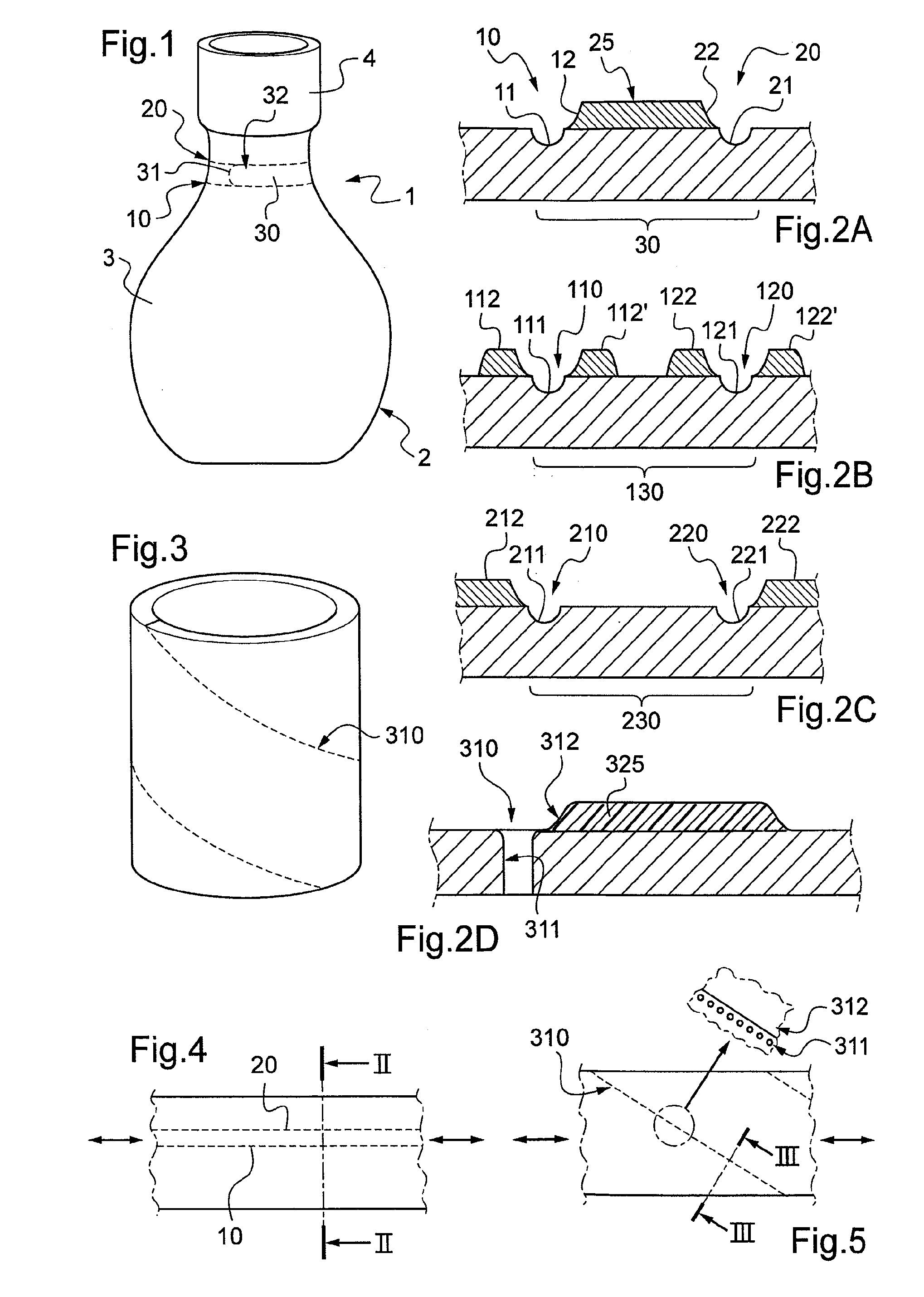
[0029]In a first embodiment shown in FIG. 2A, two lines of weakness 11, 21 are made in the film, in this example by laser cutting to half-depth in the thickness of the film (for reasons of simplification, the film is shown as comprising a single layer, but that is not limiting, and the film could comprise a plurality of layers). In the figure, there can be seen the furrows left by the cutting. Then, according to the invention, a layer of polymer varnish 25 is applied to the surface of the film so as to form a strip that extends between the lines of weakness 11, 21 up to the vicinity thereof so as to form local extra thicknesses 12, 22 bordering the lines of weakness 11, 21. Associating a line of weakness with an adjacent local region of extra thickness defines a tear line along which the sleeve can be torn. The two tear lines as defined in this way define between them the tear strip 30.

[0030]When making a sleeve, the film as prepared in this way is subjected to heat-shrinking, inclu...

second embodiment

[0034]In a second embodiment shown in FIG. 2B, tear lines 110, 120 are formed by making lines of weakness 111, 121 in the film that are bordered by local regions 112, 112′ of extra thickness that extend on either side of the line of weakness 111, and local regions 122, 122′ of extra thickness that extend on either side of the line of weakness 121. Between them, the two lines of weakness 110, 120 define a tear strip 130. In this embodiment, as in the above-described embodiment, the lines of weakness are made by laser cutting to half-depth, while the regions of local extra thickness are made by applying polymer varnish.

third embodiment

[0035]In a third embodiment shown in FIG. 2C, the tear lines 210, 220 comprise lines of weakness 211, 221 bordered on the outside of the tear strip 230 by local regions 212, 222 of extra thickness.

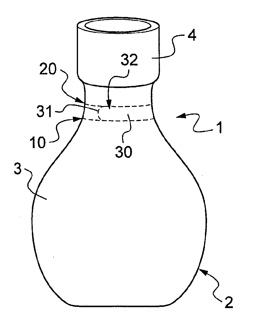
[0036]Although in these examples, the tear line extends parallel to the stretch direction of the film, this configuration is not essential. As shown in FIG. 5, it is possible to make a film with a tear line 310 that extends obliquely relative to the stretch direction of the film. As shown in FIG. 3, such a film enables sleeves to be made in which the tear line extends along a spiral, thus making it possible, on initiating tearing at the top of the sleeve, to separate the sleeve entirely from the container.

[0037]As shown in FIG. 2D, the tear line 310 includes both a weakness line 311, constituted by a sequence of microperforations in alignment, and also a local region 312 of extra thickness bordering the line of weakness 311.

[0038]Thus, making a local region of extra thickness on the stretc...


PUM

PropertyMeasurementUnit
thicknessaaaaaaaaaa
shrinkage ratioaaaaaaaaaa
mechanical weaknessaaaaaaaaaa

Abstract

The invention relates to a film of plastics material stretched to present a privileged shrinkage orientation and used in particular for fabricating heat-shrink sleeves, the film including at least one line of mechanical weakness and at least one local region of extra thickness extending along the line of weakness so as to border it, the line of weakness and the adjacent local region of extra thickness together defining a tear line. According to the invention, the local region of extra thickness is constituted by applying liquid or semi-liquid material to the film, the applied material being applied to the film in a quantity that depends on the expected shrinkage ratio in the portion of the film that includes the tear line while a sleeve made using such a film is being heat-shrunk onto an article.

Description

CROSS REFERENCE TO RELATED APPLICATIONS[0001]This application is entitled to the benefit of and incorporates by reference essential subject matter disclosed in French Patent Application No. 10 50283 filed on Jan. 15, 2010.FIELD OF THE INVENTION[0002]The invention relates to a film of single-oriented plastics material for fabricating a tearable heat-shrink sleeve, and to a heat-shrink sleeve made from such a film.TECHNOLOGICAL BACKGROUND OF THE INVENTION[0003]Heat-shrink sleeves are known that are constituted by a film of single-oriented plastics material that has previously been stretched in a determined direction in order to give it a capacity for shrinkage under the effect of heat in the stretching direction. Such sleeves are used in particular for covering the walls of containers of all kinds.[0004]It would be advantageous to give such sleeves a capacity for tearing along a privileged tear line. For example, a sleeve of this type could be used for covering the wall of a container...

Claims


Application Information

Patent Timeline
Patent Type & Authority Applications(United States)
IPC IPC(8): B65B53/00B65D65/28
CPCB29C59/007B29C61/02B29C61/0608Y10T428/1328B65D55/0854Y10T428/15B65D23/0878
Inventor FRESNEL, ERIC
Owner SLEEVER INT
Why Eureka
Try Eureka