Superconducting electricity transmission system

a superconducting, electricity transmission technology, applied in the direction of superconducting magnets/coils, superconductor devices, magnetic bodies, etc., can solve the problems of increasing the cost of the overall system, not being able to provide an alternate path for power flow,

Inactive Publication Date: 2011-07-21
AMERICAN SUPERCONDUCTOR
View PDF4 Cites 28 Cited by
  • Summary
  • Abstract
  • Description
  • Claims
  • Application Information

AI Technical Summary

Benefits of technology

[0014]In another embodiment of the present disclosure, a method for providing redundancy in a superconducting power grid is provided. The method may include providing a first AC/DC converter configured to receive a first alternating current having a first phase, a second AC/DC converter configured to receive a second alternating current having a second phase, and a third AC/DC converter configured to receive a third alternating current having a third phase. The method may further include connecting, via a first pair of superconducting DC cables, the first AC/DC converter and the second AC/DC converter, the first pair of superconducting DC cables including a first positive polarity cable and a first negative polarity cable. The method may also include connecting, via a second pair of superconducting DC...

Problems solved by technology

In some cases, however, such as the case of a ring bus topology, the overall grid may not be capable of providing a...

Method used


Image

  • Superconducting electricity transmission system
  • Superconducting electricity transmission system
  • Superconducting electricity transmission system

Examples


Embodiment Construction

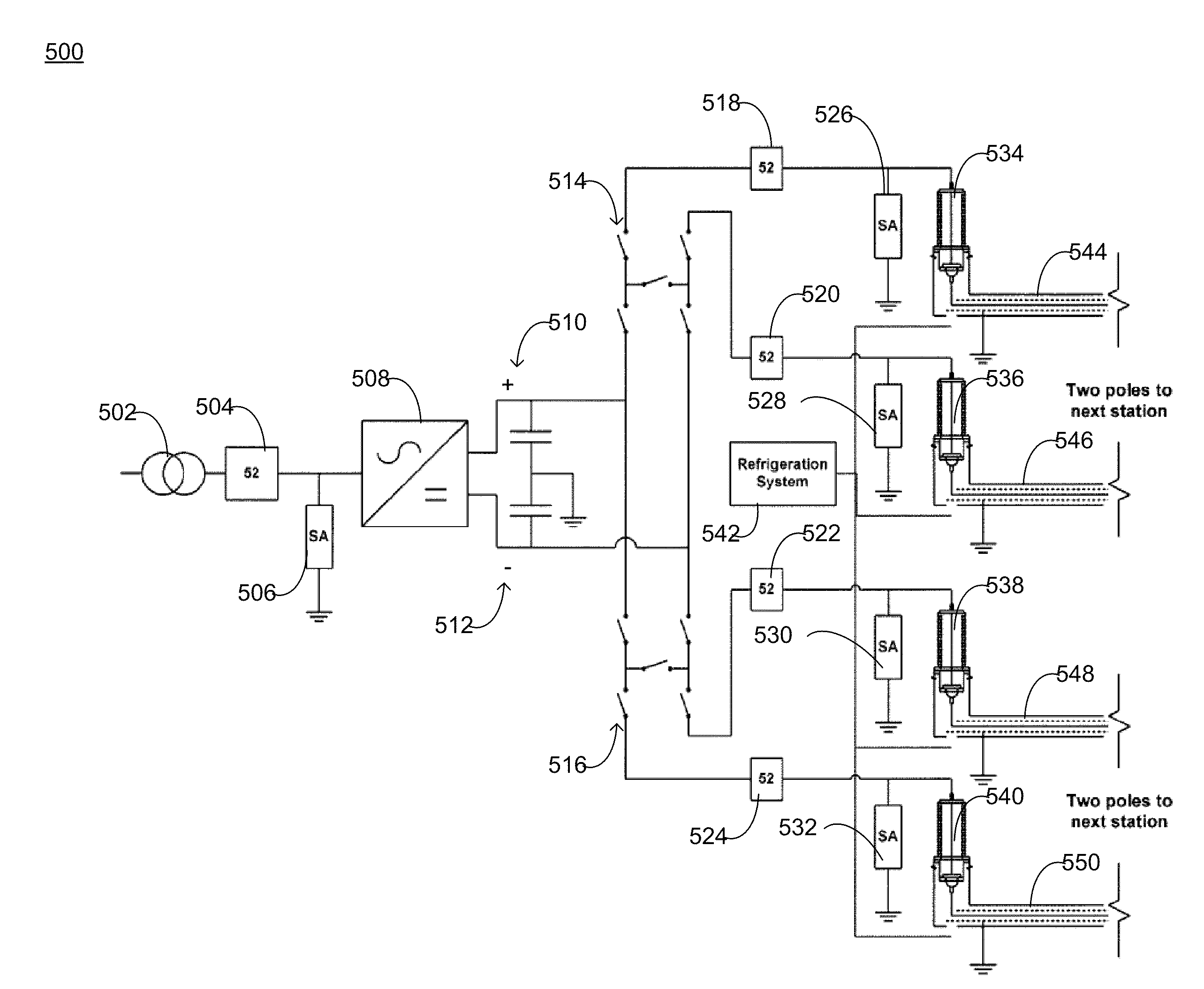
[0027]Generally, the present disclosure is directed towards a redundant electricity transmission system. The embodiments described herein may be used to connect multiple AC grids, which may or may not be out-of-phase or at different frequencies. The present disclosure allows for two separate cables (i.e., one positive and one negative) between each of a number of AC / DC terminals, to limit the possibility of a pole to pole fault. The embodiments of the present disclosure may permit for the failure of any two of the cables while allowing the overall system to continue operation. The present disclosure also provides redundancy with regard to any potential failures in the cryogenic cooling system associated with the electricity transmission system.

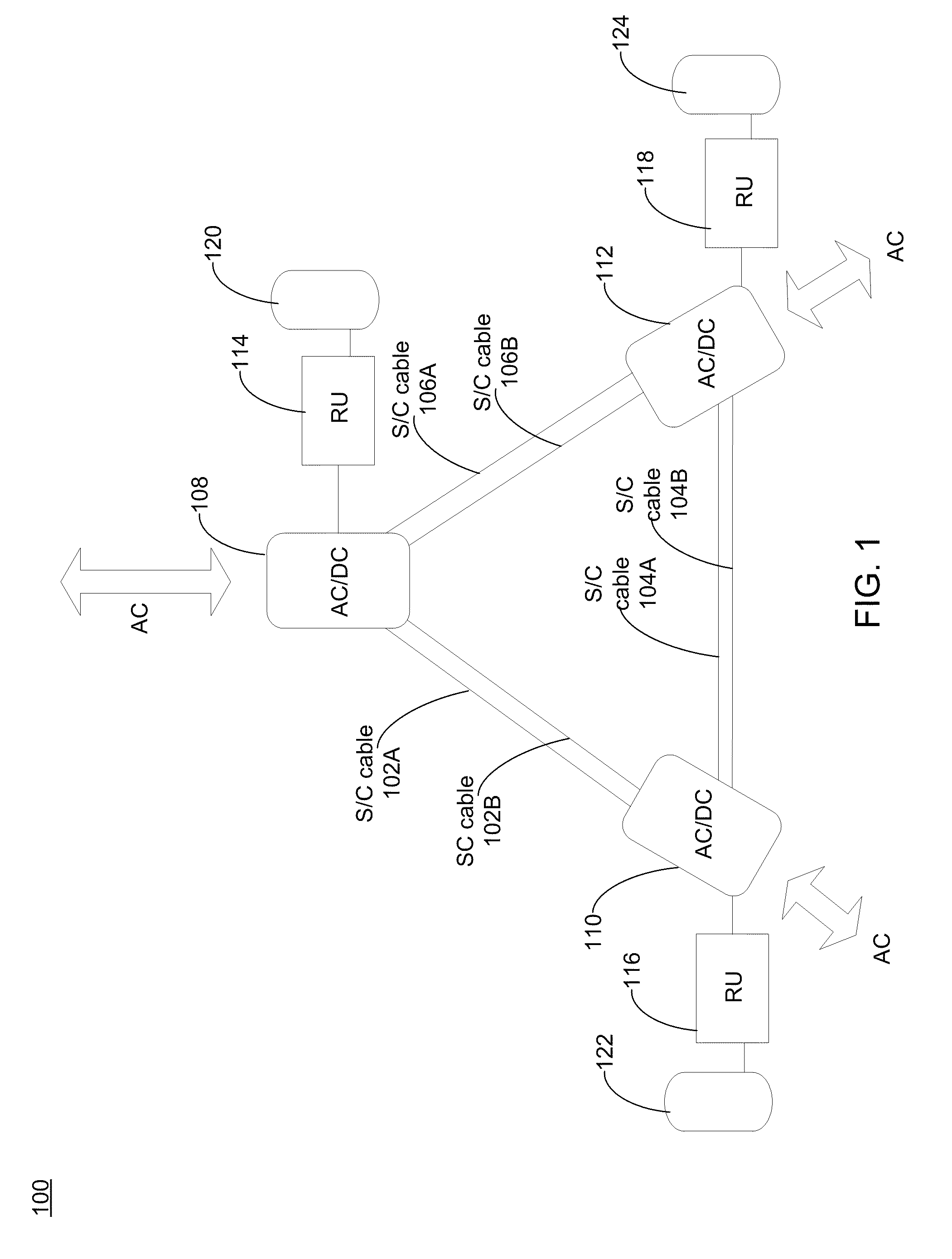
[0028]Referring to FIG. 1, a portion of a utility power grid 100 may include a high temperature superconductor (HTS) cable 102. In this particular embodiment, a DC cable system is provided depicting a two-pole (positive and negative) configura...


PUM


Abstract

The present disclosure generally relates to a superconducting power grid having one or more AC/DC converters. The superconducting grid may further include one or more pairs of superconducting DC cables connecting each AC/DC converter. Each pair of superconducting DC cables may include a first positive polarity cable and a first negative polarity cable. The grid may also include at least one switching device configured to operatively connect at least one of the first and second AC/DC converters with at least one of the pairs of superconducting DC cables, the switching device further configured to adjust the polarity of at least one of the polarity cables. Other embodiments and implementations are also within the scope of the present disclosure.

Description

CROSS-REFERENCE TO RELATED APPLICATION[0001]This application claims the benefit of U.S. provisional patent application Ser. No. 61 / 296,770, filed on 20 Jan. 2010, the entire disclosure of which is incorporated herein by reference.TECHNICAL FIELD[0002]This disclosure relates to electricity transmission systems and, more particularly, to an electricity transmission system including a cryogenic cooling system for high temperature superconductor (“HTS”) devices, such as HTS power cables.BACKGROUND[0003]Superconductivity refers to a state of materials in which the electrical resistance becomes zero when the material is cooled to a sufficiently low temperature, referred to as the critical temperature. One type of superconductor, referred to as a high temperature superconductor (HTS), has a critical temperature in excess of the boiling point of liquid nitrogen of about 77K at atmospheric pressure.[0004]The use of superconductive materials and, in particular, superconducting cables, is adva...

Claims


Application Information

Patent Timeline
IPC IPC(8): H01L39/02H02M7/02H05K7/20H01L39/18
CPCH02J3/36Y02E40/60Y02E60/60H02J5/00
Inventor GAMBLE, BRUCEMADURA, DAVIDWINN, PETERYUAN, JIE
Owner AMERICAN SUPERCONDUCTOR
Why Eureka
Try Eureka