Low-profile intravenous catheter device

a catheter device, low-profile technology, applied in the direction of trocar, other medical devices, infusion needles, etc., can solve the problems of inability to safely and comfortably infusion, inability to prevent the inability to intubate, and the above-described problems associated with the use of intravenous catheters, so as to reduce the likelihood of combative patients having to be restrained, reduce the likelihood of intubation, and reduce the effect of costs

Active Publication Date: 2011-07-21
RAWLS JAMES T
View PDF30 Cites 31 Cited by
  • Summary
  • Abstract
  • Description
  • Claims
  • Application Information

AI Technical Summary

Benefits of technology

[0008]Advantages of the intravenous catheter device and system of the present invention include the following: 1) permits safe and comfortable infusion of intravenous fluids into a patient; 2) permits movement of the patient's joints without causing kinking of the catheter tubing or dislodgement of the intravenous catheter; 3) includes a length of non-kinking tubing that can be bent into an appropriate shape on the patient's body part so that the present intravenous catheter device maintains a low-profile against the patient's body; 4) decreases the likelihood that a combative patient will have to be restrained because of concern about dislodgement

Problems solved by technology

Unfortunately, this happens frequently because of the fact that the veins that are most accessible to health care professionals are the ones in the patient's hand, wrist, and inner elbow (antecubital fossa), where there is much movement.
The catheter of a conventional IV system is prone to being inadvertently bumped, snagged, and hit on objects because of the way the regular tubing that lea

Method used


Image

  • Low-profile intravenous catheter device
  • Low-profile intravenous catheter device
  • Low-profile intravenous catheter device

Examples


Embodiment Construction

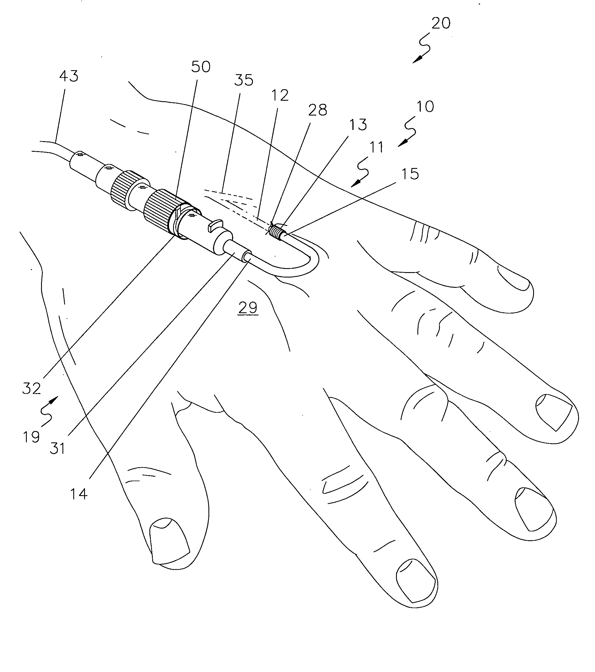
[0020]In the following description, like reference characters designate like or corresponding parts throughout the several views. Also, in the following description, it is to be understood that such terms as “over,”“under,”“within,” and the like are words of convenience and are not to be construed as limiting terms. Referring in more detail to the drawings, a device embodying the principles and concepts of the present invention and generally designated by the reference numeral 10 will now be described.

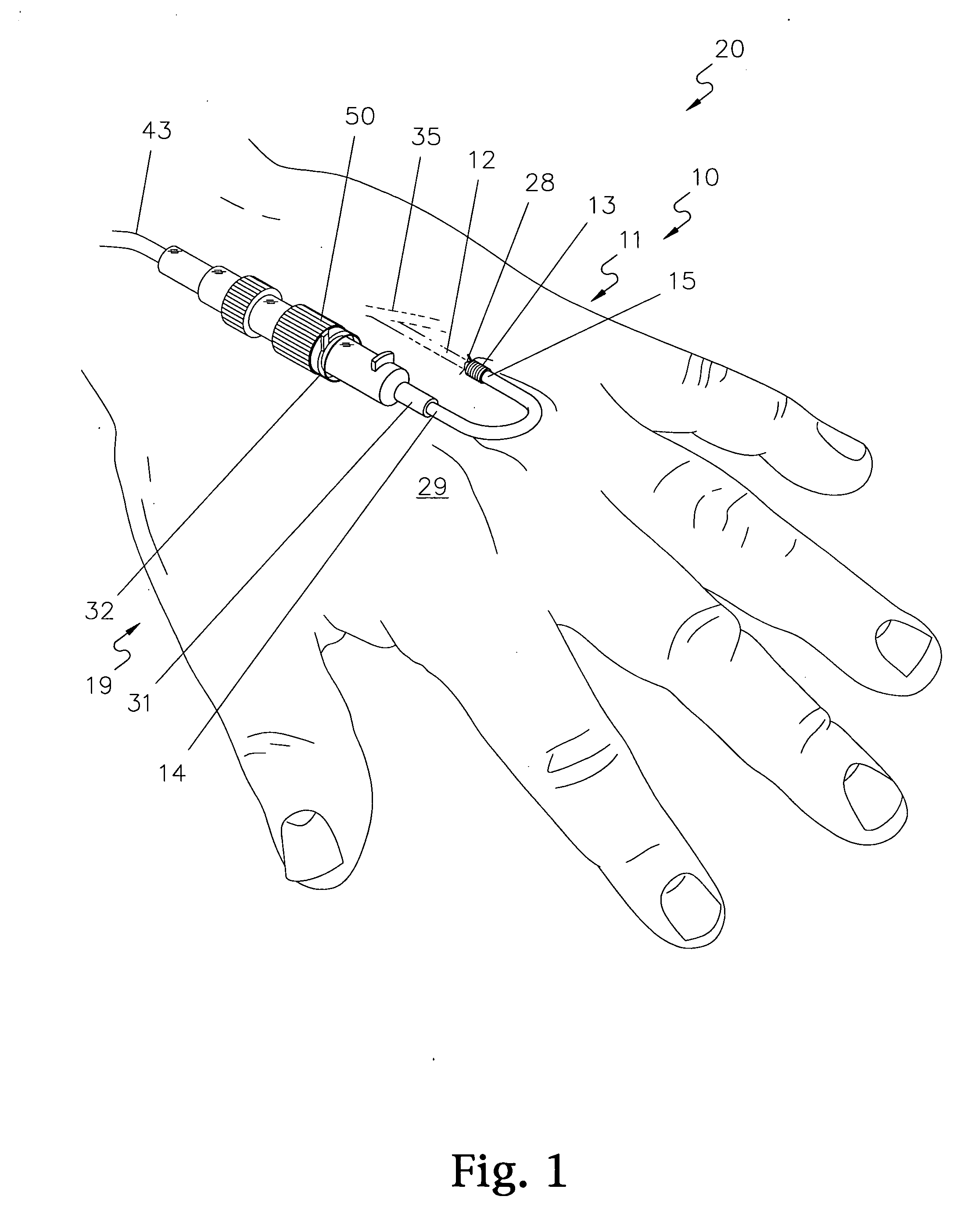
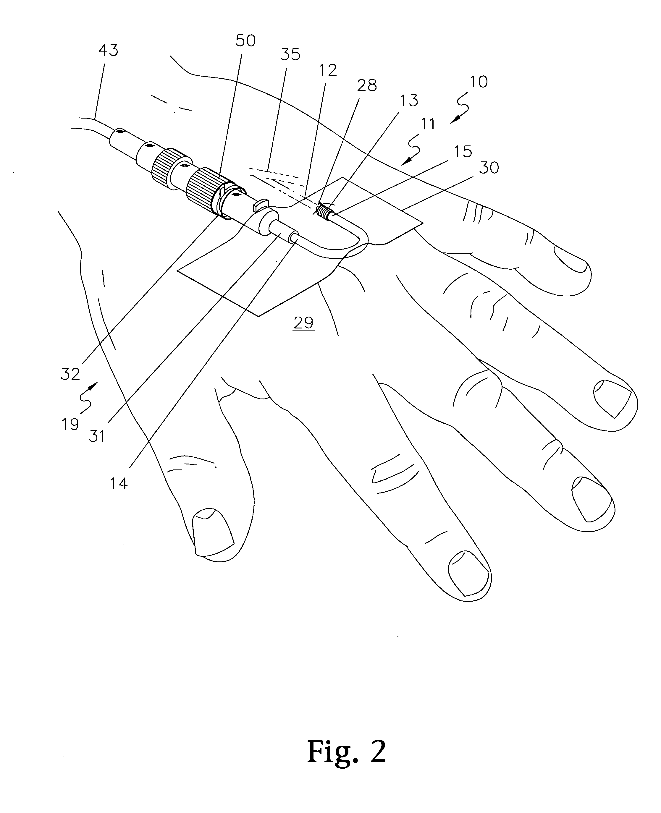
[0021]Turning first to FIGS. 1 through 4, an intravenous catheter device 10 herein comprises: (a) a medical tubing connector, preferably a leak-free screw-type connector 19; (b) a length of flexible, non-kinking, supported medical tubing 11, a first end 14 of which is connected to a first end 31 of the screw-on connector 19; (c) an intravenous catheter portion 12 at an opposite, second end of the intravenous catheter device 10, a first end 16 of which is connected to a second end 15 of...


PUM


Abstract

An intravenous catheter device and system includes: (a) a medical tubing connector at a first end of the intravenous catheter device; (b) a length of flexible, non-kinking, supported medical tubing, a first end of the non-kinking tubing being connected to a first end of the medical tubing connector; (c) an intravenous catheter portion having a first end attached to a second end of the non-kinking tubing, the non-kinking tubing extending between the intravenous catheter portion and the tubing connector; and (d) a cylindrical-shaped cuff attached to a first outside end portion of the intravenous catheter portion, and a second outside end portion of the non-kinking tubing; wherein a central channel of the intravenous catheter portion is in fluid communication with a channel of the non-kinking, flexible tubing when the intravenous catheter device is in use. This simplified abstract is not intended to limit, and should not be interpreted as limiting, the scope of the claims.

Description

BACKGROUND OF THE INVENTION[0001]1. Technical Field[0002]The present invention relates to a low-profile, non-kinking intravenous catheter device that includes a section of flexible yet supported intravenous tubing for conducting fluids into a patient's blood vessel or the like.[0003]2. Background Information[0004]Various types of intravenous (“IV”) catheters are well known in the medical field and are used throughout the world. Intravenous catheters are used for a wide variety of applications, including hydration and administration of intravenous fluids, medications, feeding, and transfusions. A typical intravenous system utilizes a needle for penetrating the skin and vein, and a catheter that remains in the patient's blood vessel for a time once the needle is removed. A catheter is a cylindrical tube made of a thin, stiff plastic-type material. The intravenous catheter slides over the needle into the vein once the needle has punctured the vein. The needle is then removed, leaving t...

Claims


Application Information

Patent Timeline
IPC IPC(8): A61B17/34A61M39/10
CPCA61M5/158A61M25/0017A61M25/0052A61M25/0097A61M25/0606A61M39/12A61M2005/1587A61M2025/0059A61M2025/006A61M25/0054A61M25/04A61M25/0693A61M2025/0293
Inventor RAWLS, JAMES T.
Owner RAWLS JAMES T
Why Eureka
Try Eureka