
Service panel with microprocessor

a microprocessor and service panel technology, applied in the direction of electric controllers, program control, instruments, etc., can solve the problems of virtually impossible to close the valve within a short period of time, the switch remains in the off position, and the access is denied, so as to achieve the effect of ease of maintenan

Active Publication Date: 2011-07-21
ISIMET MAPA
View PDF29 Cites 16 Cited by
  • Summary
  • Abstract
  • Description
  • Claims
  • Application Information

AI Technical Summary

Benefits of technology

[0020]The present invention comprises a control device that permits a single operator to turn ON circuits that control these utilities or equipment while permitting any user to turn OFF the same circuit. This method of operation will make the work environment safe in which it functions. In addition, the control device has the capability to be integrated with various types of building automation, operating and monitoring systems so that strategic electronic inputs from those systems will effect operation and some control of the device.

Problems solved by technology

On the other hand, when a service is not needed, the switch remains in the OFF position and access is denied.
However, there are several disadvantages associated with this type of control means.
If an emergency arises, it may be virtually impossible to close the valve within a short period of time.
However, with these described restrictions to access, if an emergency arises it would become necessary for the instructor to first unlock the containment area before the switch could be turned OFF and the service deactivated.
Also, if the instructor were to be called away from the classroom momentarily, then there would be no means of quickly deactivating the service in the event of an emergency.
Not only would this configuration create a potential hazard, but also it restricts future repositioning and arrangement of the classroom.
If any emergency arose during these times, then the possibility of a catastrophe is increased.
More specifically, if the service was not deactivated, and near the end of the school day a student inadvertently leaves a cold water faucet opened at a sink, that has a clogged drain that prevents the drainage of the water from the sink, by the beginning of the next school day a tremendous amount of water damage could occur within the classroom.
Further, if the event occurred prior to an extended weekend or holiday, then this damage could likely extend to the entire school.
An even more dangerous situation would exist if a gas valve was left open.
The results of such an event could be catastrophic.
Though this “EMS” does have the capability to regulate time intervals when services can be activated, there may not exist a common link between the “EMS” and the activating switches for science classroom services.
However, every instance that at first appears to be an emergency situation may not actually be an emergency.

Method used


Image

  • Service panel with microprocessor
  • Service panel with microprocessor
  • Service panel with microprocessor

Examples


Embodiment Construction

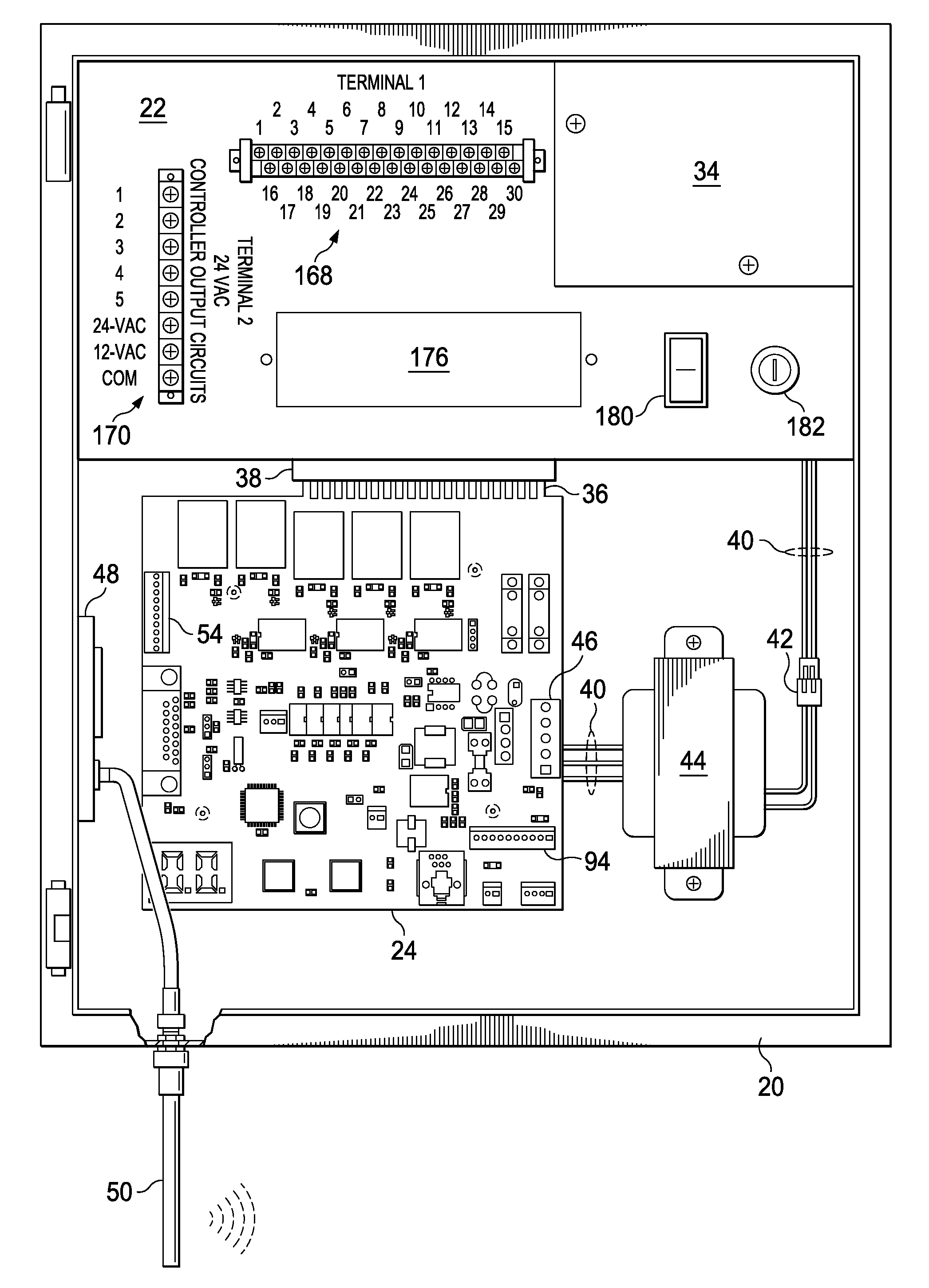
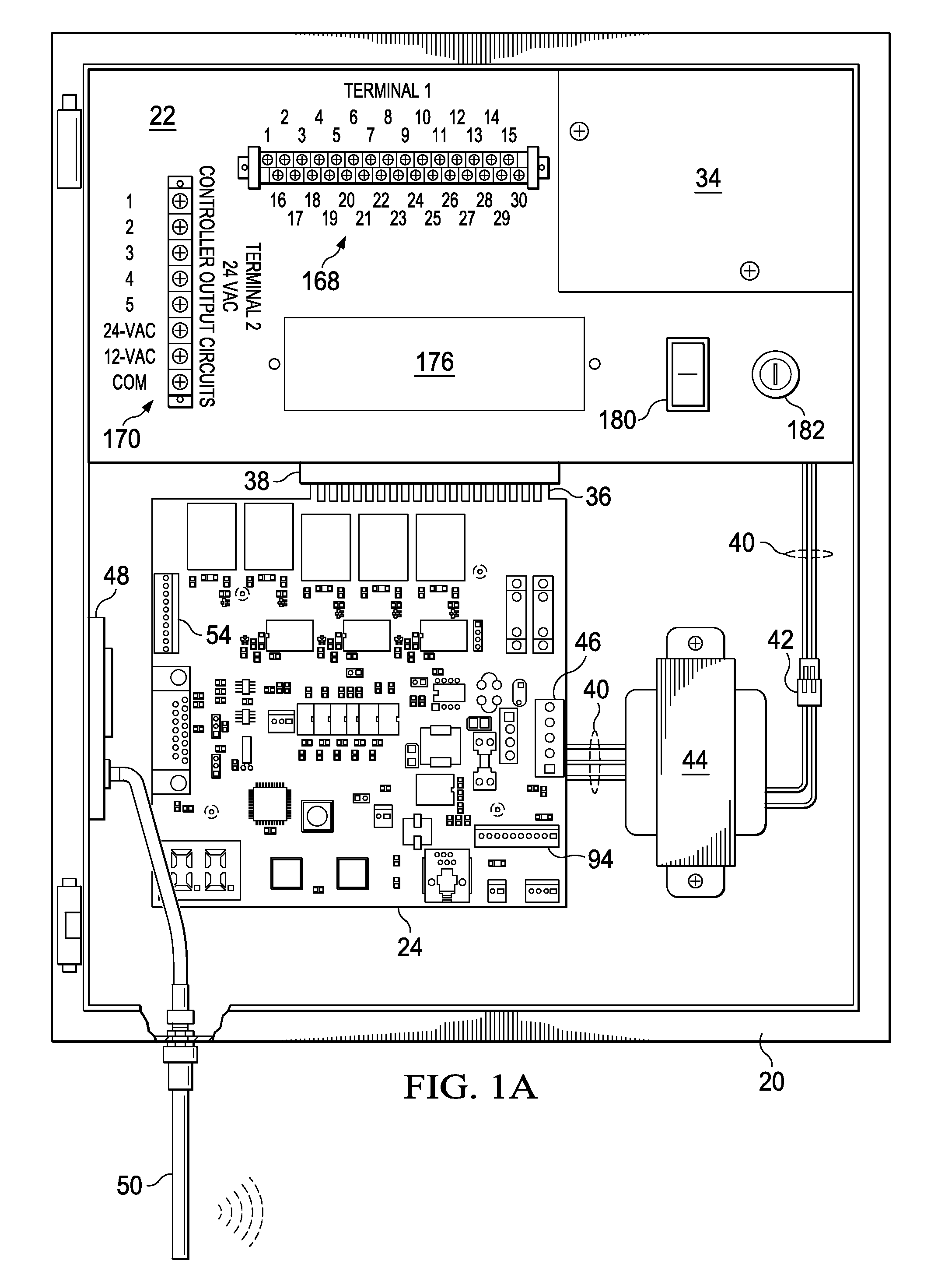
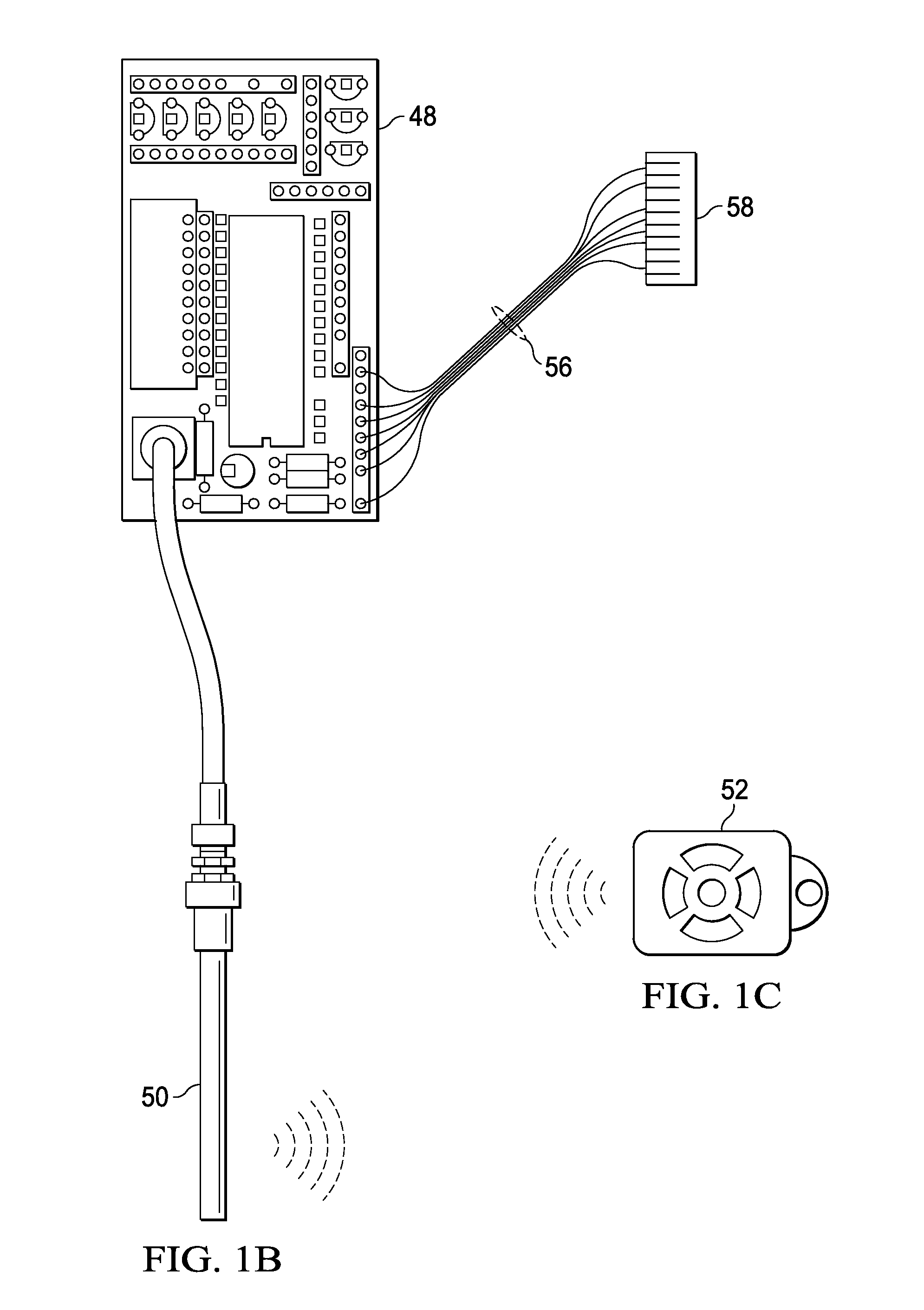
[0057]As shown in FIG. 1A the present invention is a service panel 20 having a Control Panel 22 that supports a PCB 24 (printed circuit board 24) controlled by a microprocessor. The service panel 20 controls the various services typically used in a science classroom. The panel, doors and other components are preferably constructed of welded sheet metal, and contain the various components needed for the control of selected utilities.

[0058]FIG. 2A illustrates a cut-away isometric view of the Service Panel enclosure 26 with the Control Panel 22 mounted in position. There is also shown a J-Box (jumper box) side 28 positioned (as an example only) in the upper corner that creates an area J-Box 30 in the void between the side piece 28, the Control Panel 22 and the adjoining sides of the enclosure 26. In this figure as well as the side view (FIG. 2B) of the enclosure 26, discussed below, the Control Panel 22 may be secured in the enclosure 26 by welding, with pop rivets 32 or any other suit...


PUM


Abstract

A service panel for limiting access to authorized persons. A sub-region of the service panel controls at least one electrically-operated (e.g., solenoid-operated) valve that is connected to service utilities (e.g., water or gas) piping so as to control flow through the valve. According to one embodiment, another sub-region (i.e., a utility controller region) contains a PCB and other electrical controls for controlling the valve(s) and communicating with other services such as a remote transmitter, or an auxiliary monitoring system (e.g., a fire alarm system). The service panel facilitates the use of advantageous features including: emergency shutdown by anyone while permitting reset only by authorized personnel; modular construction so as to facilitate installation of the system. Various jumper terminals and connecting wires provide for programming of the system to accommodate a variety of applications.

Description

[0001]This application claims the benefit of U.S. provisional application No. 61 / 295,948, filed on Jan. 18, 2010, entitled “Service Panel with Utility Controller,” and U.S. application Ser. No. 10 / 310,491, filed Dec. 5, 2002, now U.S. Pat. No. 6,757,589, both of which are incorporated herein by reference.BACKGROUND[0002]This invention relates to controlling utility services within buildings and more particularly to the control of such utility services. As examples, control of utility services within buildings is disclosed in U.S. Pat. No. 5,267,587 granted to Geoffrey P. Brown on Dec. 7, 1993 and U.S. Pat. No. 5,331,619 granted to Thomas G. Barnum, et al., on Jul. 19, 1994. Plumbing and electrical service within commercial and / or public building structures is typically required to be provided with a means of control so that individual areas receiving these services can be isolated from other areas of the building for the purposes of repair.[0003]A common method for this isolation of...

Claims


Application Information

Patent Timeline
Patent Type & Authority Applications(United States)
IPC IPC(8): G05B15/02
CPCG05B15/02G05B2219/2642G05B2219/24146G05B2219/24003
Inventor PARKER, PHIL A.
Owner ISIMET MAPA
Learn More