Supercharge Your Innovation With Domain-Expert AI Agents!

Delivery position aligning method for use in vacuum processing apparatus, vacuum processing apparatus and computer storage medium

a technology of vacuum processing apparatus and position alignment, which is applied in the direction of transportation and packaging, semiconductor/solid-state device testing/measurement, instruments, etc., can solve the problems of deteriorating accuracy errors of delivery position coordinates, and long transfer distance of substrate to orienter, etc., to improve the accuracy of delivery position

Active Publication Date: 2011-07-21
TOKYO ELECTRON LTD
View PDF4 Cites 5 Cited by
  • Summary
  • Abstract
  • Description
  • Claims
  • Application Information

AI Technical Summary

Benefits of technology

This approach improves the accuracy of delivery position coordinates by shortening transfer distances and reducing positional errors, ensuring precise alignment of access points within the vacuum processing apparatus.

Problems solved by technology

As a consequence, a transfer distance of the substrate to the orienter becomes long and, also, errors of delivery position coordinates of the access points (load lock chambers or the like) to which the substrate are delivered are accumulated.
As a result, the accuracy of the delivery position coordinates deteriorates.

Method used


Image

  • Delivery position aligning method for use in vacuum processing apparatus, vacuum processing apparatus and computer storage medium
  • Delivery position aligning method for use in vacuum processing apparatus, vacuum processing apparatus and computer storage medium
  • Delivery position aligning method for use in vacuum processing apparatus, vacuum processing apparatus and computer storage medium

Examples


Embodiment Construction

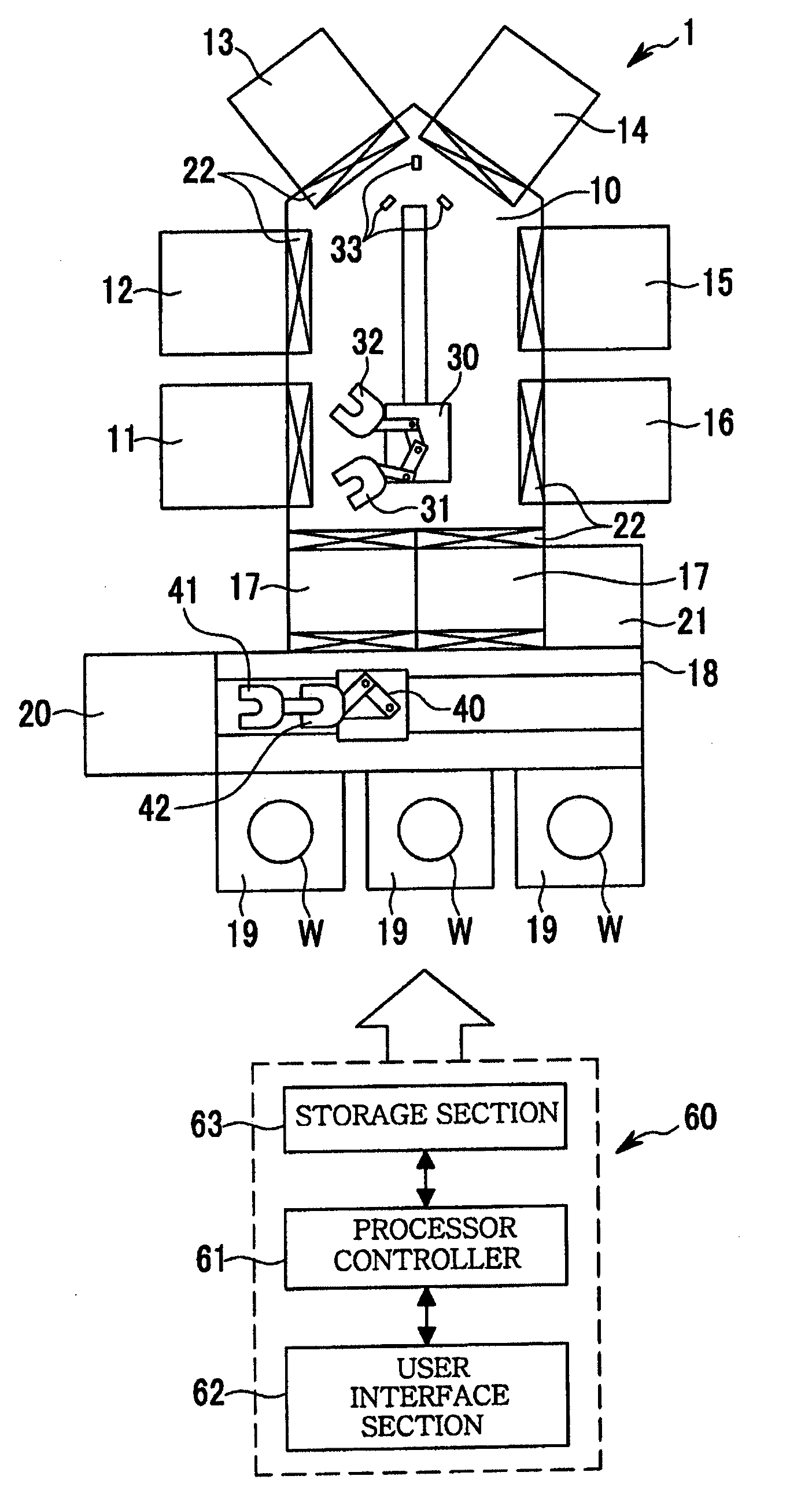
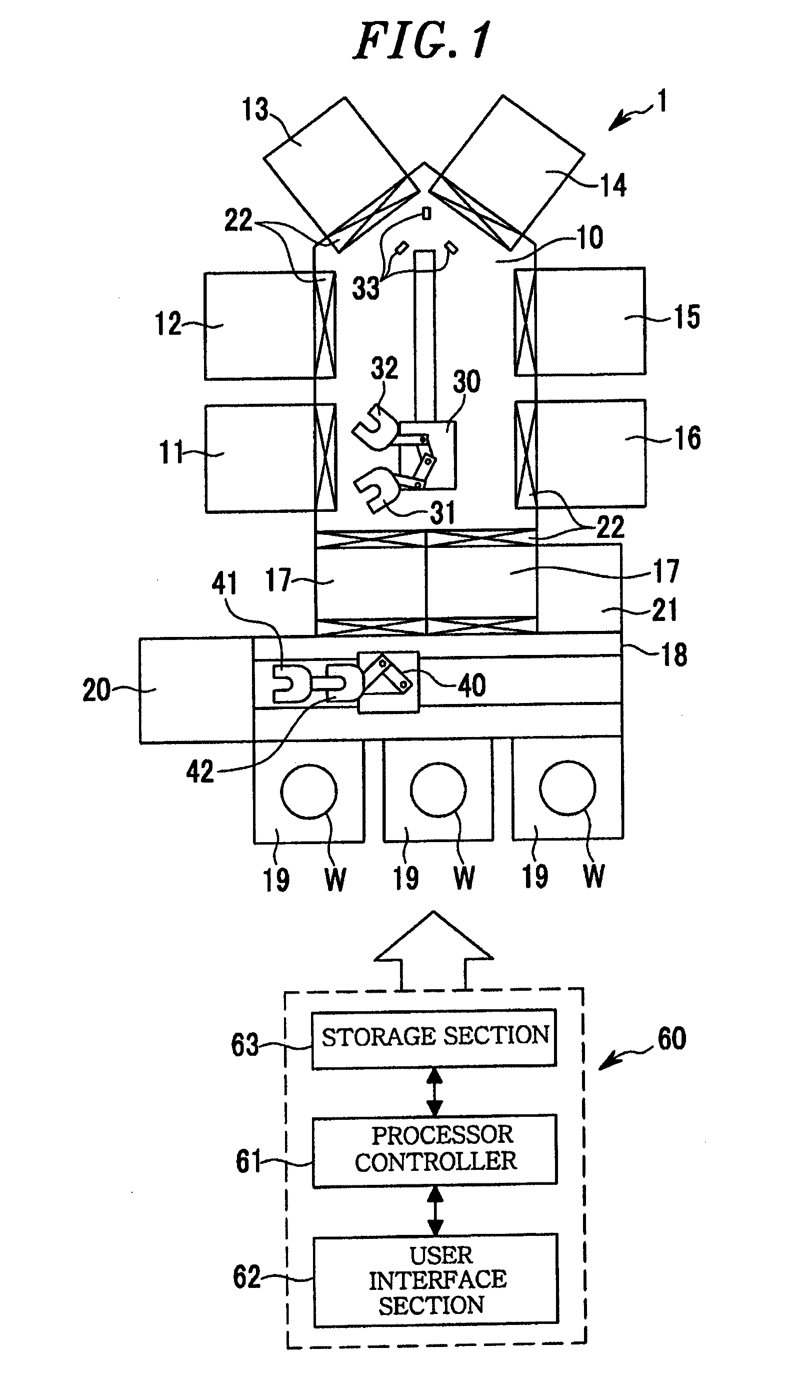
[0034]The embodiments of the present invention will be described with reference to the accompanying drawings. FIG. 1 illustrates an overall schematic configuration of a vacuum processing apparatus 1 in accordance with one embodiment of the present invention. A vacuum transfer chamber 10 is provided at a central portion of the vacuum processing apparatus 1, and a plurality of (six in this embodiment) vacuum processing chambers 11 to 16 are arranged around a periphery of the vacuum transfer chamber 10.

[0035]Two load lock chambers 17 are disposed at a front side (lower side in FIG. 1) of the vacuum transfer chamber 10, and a transfer chamber 18 for transferring substrates (semiconductor wafers W in this embodiment) in the atmosphere is arranged at a front side (lower side in FIG. 1) of the load lock chambers 17. Provided at a front side of the transfer chamber 18 is a plurality of (three in FIG. 1) mounting tables 19 on which substrate accommodating cases (cassettes or FOUPs) capable o...


PUM


Abstract

In a vacuum transfer chamber, a position detecting mechanism for detecting the positions of semiconductor wafers is arranged. The semiconductor wafers disposed at predetermined positions in a load lock chamber and vacuum processing chambers are transferred to the position detecting mechanism by a vacuum transfer mechanism and the positions of the wafers are detected. Then, based on the detection results, aligning between the load lock chamber and the vacuum processing chambers is performed.

Description

CROSS-REFERENCE TO RELATED APPLICATIONS[0001]This is a continuation application of pending U.S. application Ser. No. 12 / 094,783, filed on May 23, 2008, which is a national stage application of PCT / JP2007 / 054837, filed on Mar. 12, 2007, and which claims priority to Japanese Patent Application No. 2006-76190, filed on Mar. 20, 2006, the entire contents of each of which are hereby incorporated by reference.FIELD OF THE INVENTION[0002]The present invention relates to a position aligning method for use in a vacuum processing apparatus performing vacuum processing on a substrate such as a semiconductor wafer, a vacuum processing apparatus and a computer storage medium.BACKGROUND OF THE INVENTION[0003]Conventionally, there has been used a vacuum processing apparatus for performing vacuum processing (e.g., film formation or etching) on a substrate such as a semiconductor wafer in a vacuum atmosphere. Further, there is known a so-called multi-chamber type vacuum processing apparatus, having ...

Claims


Application Information

Patent Timeline
Patent Type & Authority Applications(United States)
IPC IPC(8): H01L21/677G06F17/00H01L21/68
CPCH01L21/67196H01L21/68H01L21/67259H01L22/00
Inventor KONDOH, KEISUKEKOIZUMI, HIROSHI
Owner TOKYO ELECTRON LTD
Features
  • R&D
  • Intellectual Property
  • Life Sciences
  • Materials
  • Tech Scout
  • Unparalleled Data Quality
  • Higher Quality Content
  • 60% Fewer Hallucinations
Learn More