Adjustable brake booster

Active Publication Date: 2011-07-21
ROBERT BOSCH GMBH
View PDF7 Cites 45 Cited by
  • Summary
  • Abstract
  • Description
  • Claims
  • Application Information

AI Technical Summary

Benefits of technology

[0009]The booster according to the present invention has means making it possible to create a non-zero offset and/or a variation, on command, for example at the command of an electronic con

Problems solved by technology

The Applicant Company has concluded from this that the dynamic equilibrium

Method used


Image

  • Adjustable brake booster
  • Adjustable brake booster
  • Adjustable brake booster

Examples


Embodiment Construction

[0054]In FIGS. 1 to 20, the same references have been used to denote elements that are the same.

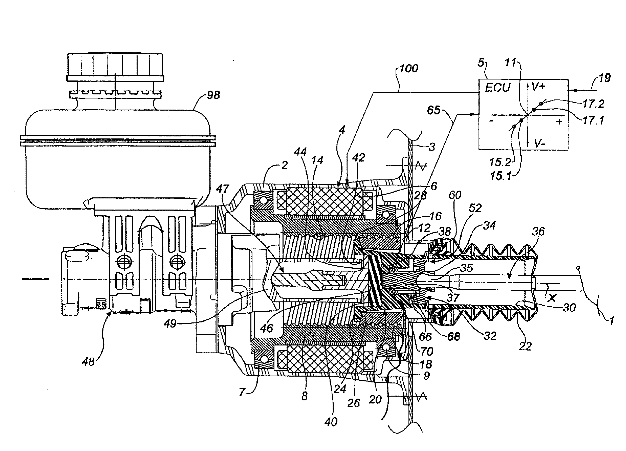
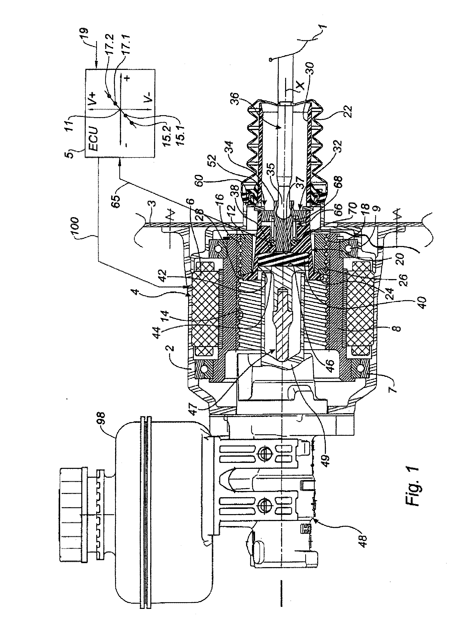
[0055]FIG. 1 shows a first embodiment according to the present invention comprising a casing 2, a rotary electric motor 4 of axis X positioned inside the casing and which is able to drive a ring 12. In the example depicted, the motor is formed of a stationary electrical element known as a stator secured to the casing 2 and of a rotationally moving electrical element known as a rotor 8 inside the stator. The stator is electrically powered, for example, by an alternator (not depicted).

[0056]The booster is attached to a bulkhead 3 that separates an engine compartment from the passenger compartment of the motor vehicle.

[0057]Because the internal structure of the rotary electric motor is well known to those skilled in the art, it will not be described further.

[0058]The rotor 8 forms a nut of a screw-nut assembly, advantageously of the type comprising balls, positioned inside the casing. The ro...


PUM


Abstract

The present invention relates mainly to a brake booster that is adjustable, notably in terms of the value of the jump.
Advantageously, according to the invention, the “target” value for equilibrium of operation of the booster actuator is altered. A target value of a signal delivered by a position sensor is defined either by programming the electronic control unit or by selecting a coefficient in a program as a function of the braking characteristic or characteristics that it is desired to implement. Once the setpoint value has been determined, the electronic control unit commands the actuator using a setpoint value so that the actuator permanently and dynamically works toward achieving the previously defined and/or selected target value. The setpoint may be calculated as a function of torque, force, position or some other parameter.
The invention applies notably to the automotive industry.
The invention applies mainly to the braking industry.

Description

BACKGROUND OF THE INVENTION[0001]The present invention relates mainly to a brake booster that is adjustable, notably in terms of the value of the jump.[0002]It is known practice to produce brake boosters that apply a force to a push rod of a master cylinder which force is an increasing function of the force applied by the driver to a control rod via a brake pedal. Typically, for a range of use, the boost ratio which is the ratio between the input force applied to the control rod and the output force from the booster and applied to the push rod, is constant. It is commonplace for several ranges of use to be employed, with several boost ratios, a first boost ratio for comfortable braking and a second boost ratio, higher than said first boost ratio, for emergency braking.[0003]Among brake boosters of the known type, mention may, nonlimitingly, be made of vacuum pneumatic brake boosters, pressurized pneumatic brake boosters, hydraulic brake boosters (also known as hydroboost brake servo...

Claims


Application Information

Patent Timeline
IPC IPC(8): B60T8/172
CPCB60T13/745
Inventor ANDERSON, CHRISCAGNAC, BASTIENSPROCQ, RAYNALD
Owner ROBERT BOSCH GMBH
Why Eureka
Try Eureka