Method for Estimating Geometric Error Between Linear Axis and Rotary Axis in a Multi-Axis Machine Tool

Inactive Publication Date: 2011-07-21
KYUNGPOOK NAT UNIV IND ACADEMIC COOP FOUND
View PDF14 Cites 25 Cited by
  • Summary
  • Abstract
  • Description
  • Claims
  • Application Information

AI Technical Summary

Benefits of technology

[0018]According to exemplary embodiments of the present invention as set forth above, the position-independent geometric error parameters can be measured taking into account the geometric error between the linear axis and the rotary axis in the multi-axis machine tool, particularly the position-dependent geometric error parameters of the drive axis. The circular path

Problems solved by technology

However, the multi-axis machine tool essentially has geometric error between the linear axis and the rotary axis because of the existence of physical defects and of limitation of assembly.
Particularly, such a geometric error becomes an important factor in determining geometrica

Method used


Image

  • Method for Estimating Geometric Error Between Linear Axis and Rotary Axis in a Multi-Axis Machine Tool
  • Method for Estimating Geometric Error Between Linear Axis and Rotary Axis in a Multi-Axis Machine Tool
  • Method for Estimating Geometric Error Between Linear Axis and Rotary Axis in a Multi-Axis Machine Tool

Examples


Example

[0027]Reference will now be made in detail to various embodiments of the present invention(s), examples of which are illustrated in the accompanying drawings and described below. While the invention(s) will be described in conjunction with exemplary embodiments, it will be understood that the present description is not intended to limit the invention(s) to those exemplary embodiments. On the contrary, the invention(s) is / are intended to cover not only the exemplary embodiments, but also various alternatives, modifications, equivalents and other embodiments that may be included within the spirit and scope of the invention as defined by the appended claims.

[0028]Throughout this document, reference should be made to the drawings, in which the same reference numerals and signs are used throughout the different drawings to designate the same or similar components. In the following description of the present invention, detailed descriptions of known functions and components incorporated h...


PUM


Abstract

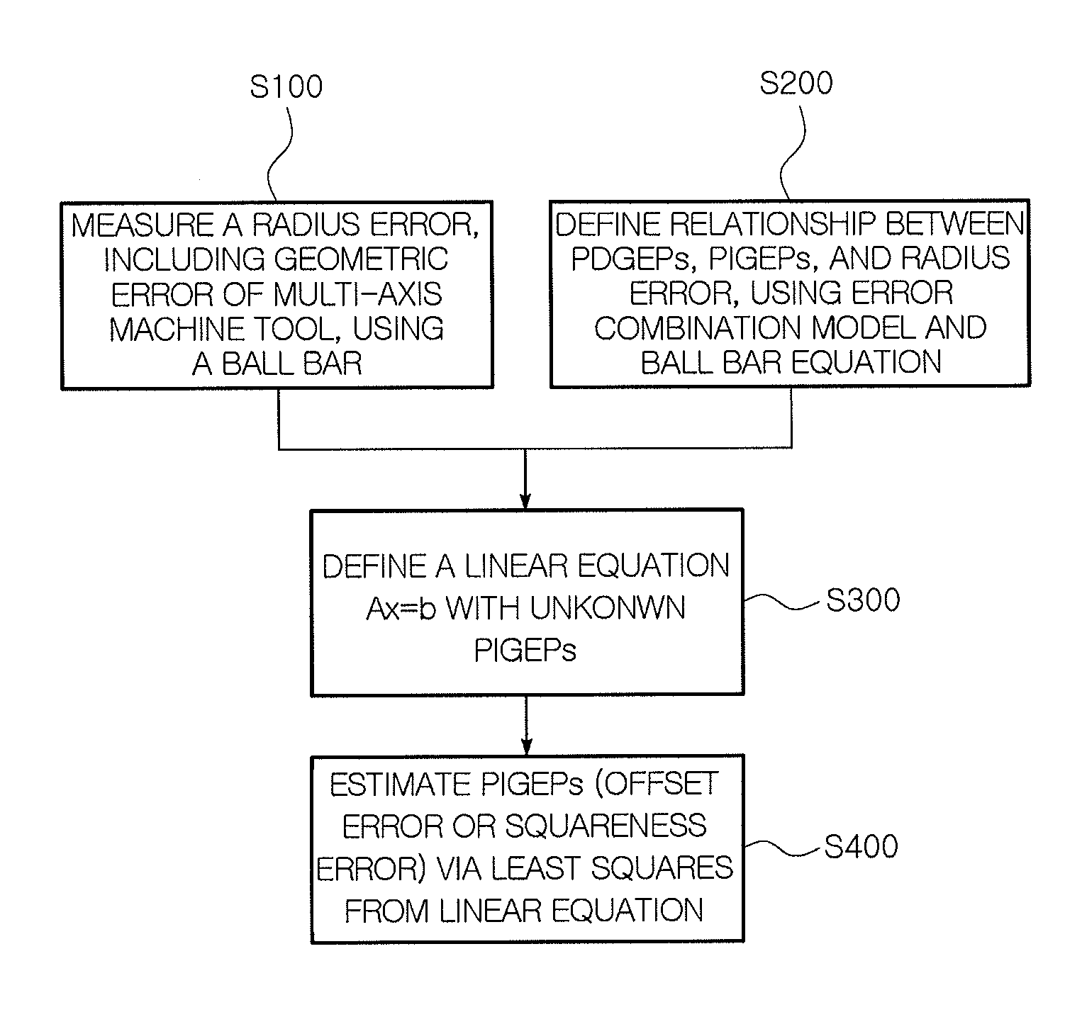
A method of estimating a geometric error between a linear axis and a rotary axis in a multi-axis machine tool is provided, the method including creating a circular path under the control of one or more drive axes and measuring a radial error of the circular path using a ball bar, defining the relationship between position-dependent geometric error parameters and position-independent geometric error parameters and measured data using an error synthesis model and an equation of a ball bar, defining a linear equation with unknown position-independent geometric error parameters by removing higher order terms of the position-dependent geometric error parameters and position-independent geometric error parameters, and obtaining the position-independent geometric error parameters through least squares from the linear equation.

Description

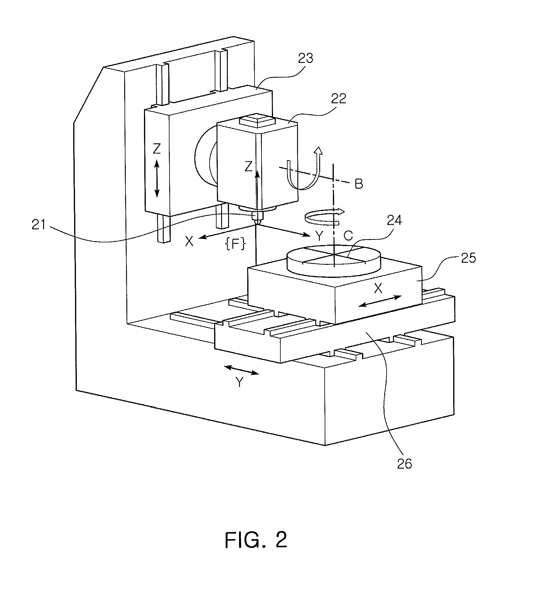
CROSS REFERENCE TO RELATED APPLICATION[0001]The present application claims priority from Korean Patent Application Number 10-2010-0004868 filed on Jan. 19, 2010, the entire contents of which application is incorporated herein for all purposes by this reference.BACKGROUND OF THE INVENTION[0002]1. Field of the Invention[0003]The present invention relates in general to a multi-axis machine tool having one or more linear axes and one or more rotary axes, and more particularly, to a method for estimating and evaluating the geometric error between a linear axis and a rotary axis.[0004]2. Description of Related Art[0005]Generally, multi-axis machine tools are machine tools having two or more drive axes, such as multi-joint robots, coordinate measuring machines (CMMs) or the like. Such multi-axis machine tools generally include one or more linear axes and one or more rotary axes. As a representative example, a 5-axis machine tool is provided, and has three linear axes and two rotary axes so...

Claims


Application Information

Patent Timeline
IPC IPC(8): G06F17/10
CPCG01B21/042
Inventor YANG, SEUNG-HANLEE, DONG-MOKLEE, KWANG-IIZHU, ZANKUN
Owner KYUNGPOOK NAT UNIV IND ACADEMIC COOP FOUND
Why Eureka
Try Eureka