Stack type heat exchanger

Inactive Publication Date: 2011-07-28
SUMITOMO PRECISION PROD CO LTD
View PDF9 Cites 19 Cited by
  • Summary
  • Abstract
  • Description
  • Claims
  • Application Information

AI Technical Summary

Benefits of technology

[0023]The heat exchanging performance of the stack type heat exchanger of the present invention is increased particularly when the hot fluid circulating in the entire area in the width direction from the outside to the inside of the U-turn passage passes through the mixing header to perform stirring and mixing. In addition, the heat exchanging performance of the counterflow type heat exchanger in which the circulation directions of the hot fluid and the fluid direction are counter is higher than that of the parallel flow type in which the circulation direction of the hot fluid and the fluid direction of the cold fluid are the same.
[0024]When the bypass mechanism is necessary, the mixing header on the advance side is used as the bypass header so that the configuration is simplified.
[0025]In the sta

Problems solved by technology

Consequently, contrary to expectations of the present inventors, by removing the bypass mechanism, the non-un

Method used


Image

  • Stack type heat exchanger
  • Stack type heat exchanger
  • Stack type heat exchanger

Examples


Embodiment Construction

[0035]Hereinafter, embodiments of the present invention will be described with reference to the drawings.

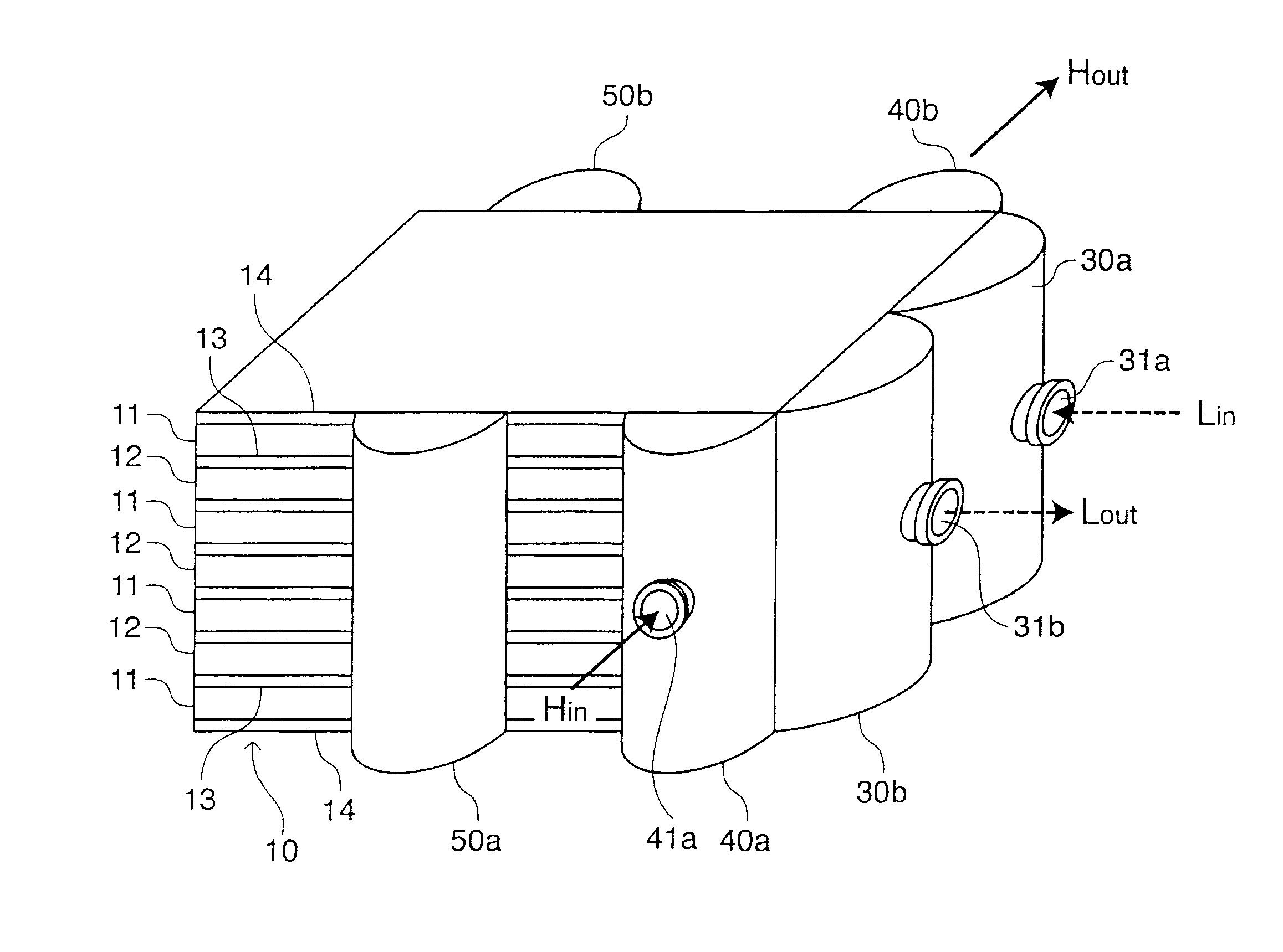
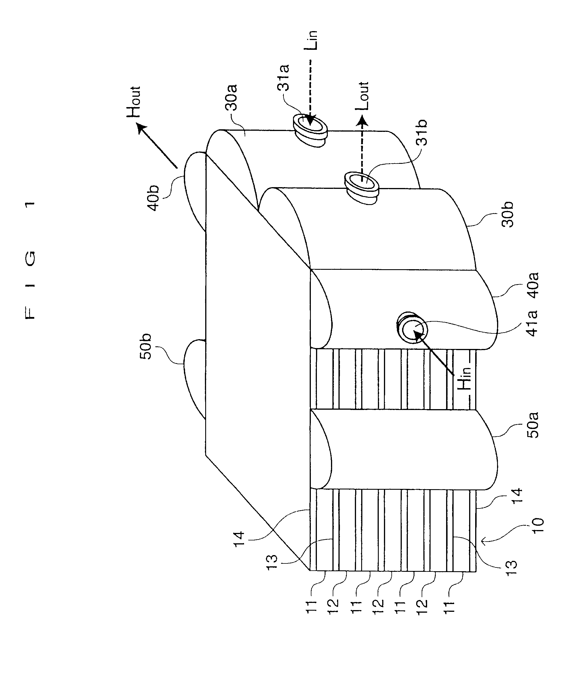
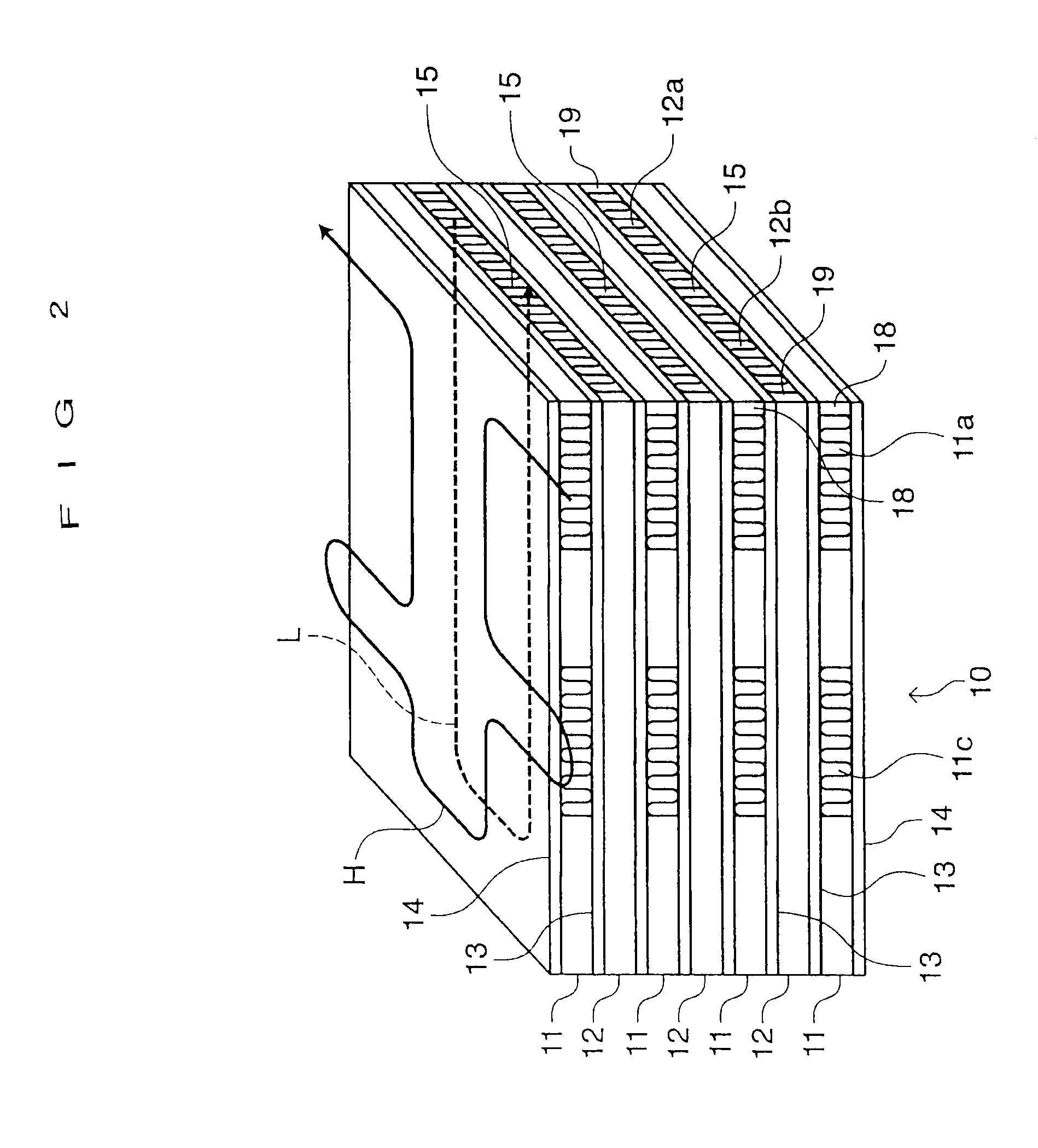
[0036]A stack type heat exchanger of this embodiment is used as an aircraft engine oil cooler, and as shown in FIGS. 1 and 2, has a rectangular cuboid stacked core 10 including a plate-fin type heat exchanger of a counterflow type. In the stacked core 10, layered hot fluid passages 11 including corrugated fins and layered cold fluid passage 12 including corrugated fins are alternately stacked. Partition plates 13 called tube plates are provided between the hot fluid passages 11 and the cold fluid passages 12, and both end faces in the stacking direction of the stacked core 10 are closed by end plates 14 called tube plates.

[0037]As shown in FIGS. 3 and 4, each of the hot fluid passages 11 and each of the cold fluid passages 12 are both of a U-turn type, and a partitioning member 15 which partitions its first half and its return path is provided in the center portion in the width d...


PUM


Abstract

The heat exchanger performance of a stack type heat exchanger used as an aircraft engine oil cooler or the like is increased. U-turn type layered hot fluid passages having corrugated fins and U-turn type layered cold fluid passages having corrugated fins are alternately stacked to configure a stacked core. Mixing headers are provided to both side surfaces of the stacked core so as to pass a hot fluid which circulates on a first half side and a return path side through the mixing headers outside of the stacked core. The mixing headers mix the hot fluid which circulates in the inside portion of the U-turn passage and the hot fluid which circulates in the outside portion thereof. The hot fluids are mixed between the plural stacked hot fluid passages. The temperature distribution of the hot fluid in the first half and in the passage width direction is made uniform.

Description

BACKGROUND OF THE INVENTION[0001](1) Field of the Invention[0002]The present invention relates to a heat exchanger suitable for an aircraft engine oil cooler. More specifically, the present invention relates to a stack type heat exchanger in which U-turn type layered hot fluid passages through which a hot fluid circulates and U-turn type layered cold fluid passages through which a cold fluid circulates are alternately stacked.[0003](2) Description of Related Art[0004]In terms of difference between media which cools an engine oil, as aircraft engine oil coolers, two types, that is, a fuel cooled type and an air cooled type, are typical. In addition, in terms of difference in configuration between heat exchangers used, two types, that is, a plate-fin type and a shell-and-tube type, are typical. Used relatively frequently among these combinations is the fuel cooled type oil cooler using the plate-fin type heat exchanger. In the fuel cooled type oil cooler, with cooling of a hot engine ...

Claims


Application Information

Patent Timeline
IPC IPC(8): F28F3/00
CPCF01M5/002F28F9/02F28D2021/0089F28D9/0068
Inventor URATA, KAZUNORITOMIDA, SUSUMUNARITA, KOUJISAKAMOTO, TAKESHI
Owner SUMITOMO PRECISION PROD CO LTD
Why Eureka
Try Eureka