Collapsible refuse bin

a bin and refuse technology, applied in the field of collapsible containers, can solve the problems of bin venting walls and not weatherproo

Active Publication Date: 2011-07-28
NOVA CHEM (INT) SA
View PDF44 Cites 29 Cited by
  • Summary
  • Abstract
  • Description
  • Claims
  • Application Information

AI Technical Summary

Benefits of technology

[0009]The current invention provides a collapsible container with an open top. The container may con

Problems solved by technology

Finally, the bin has vented w

Method used


Image

  • Collapsible refuse bin
  • Collapsible refuse bin
  • Collapsible refuse bin

Examples


Embodiment Construction

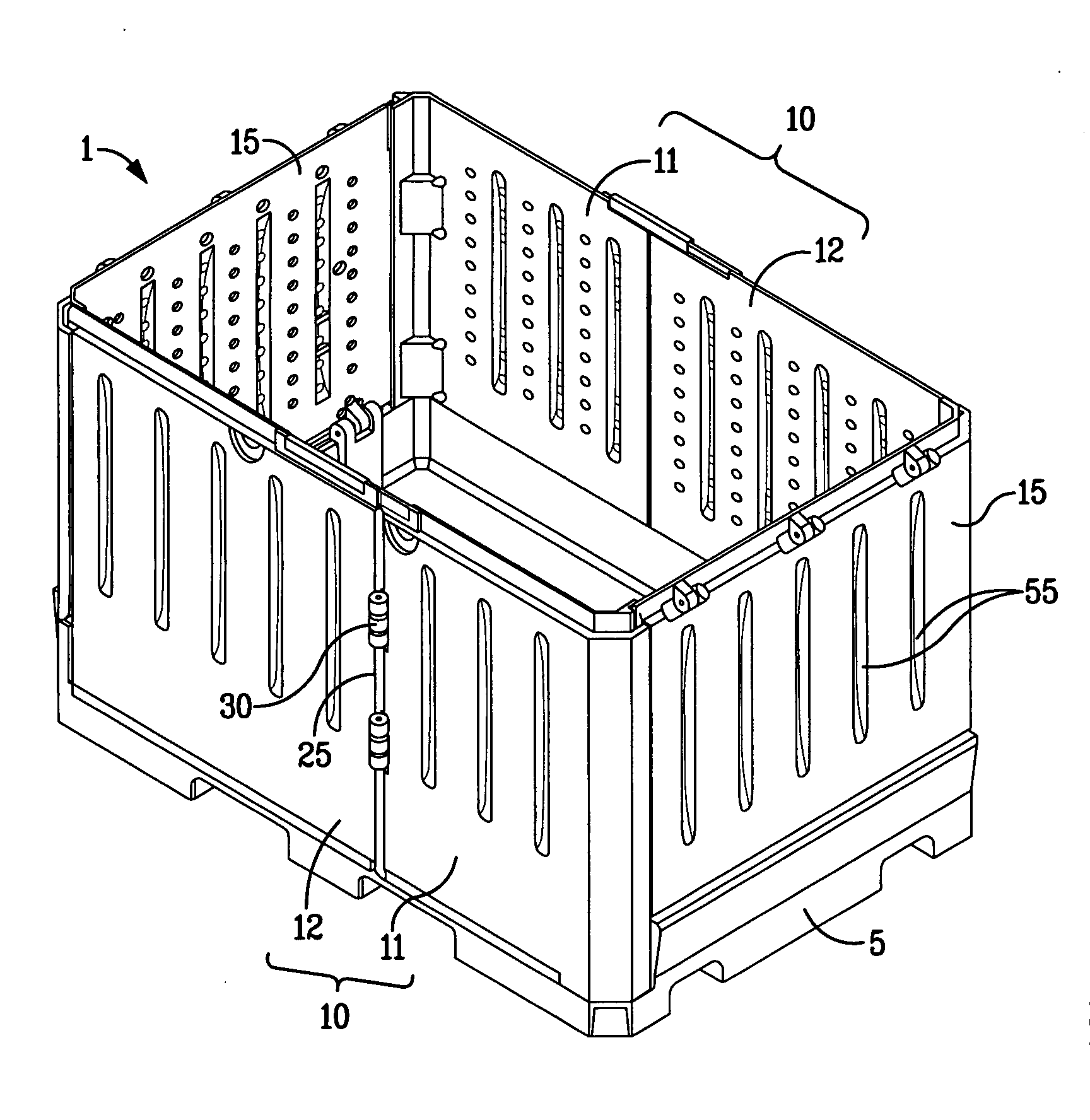
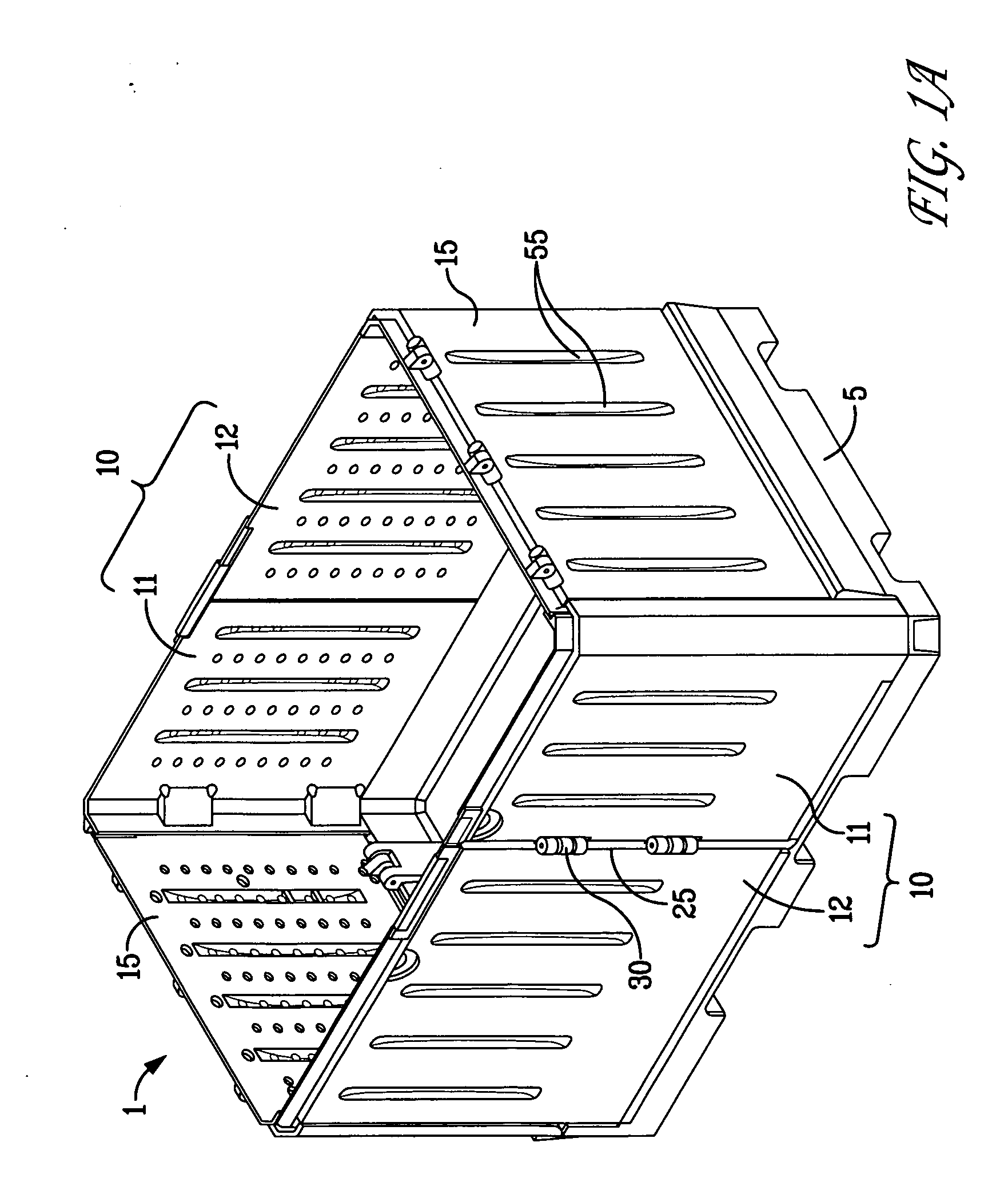
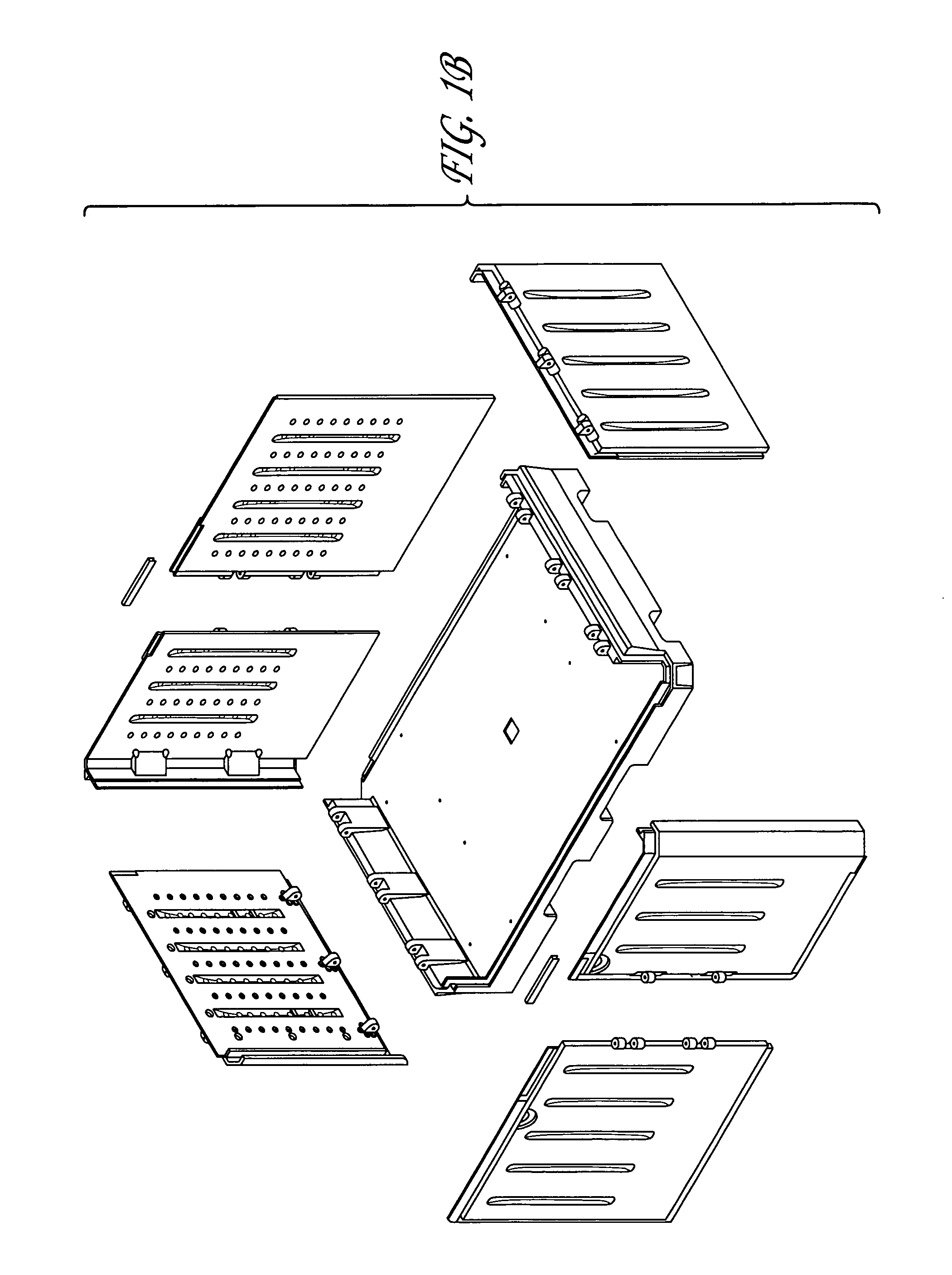
[0062]In the current invention, the use of the terms “end wall” and “side wall” is arbitrary and is used only to distinguish one set of opposing container walls from the other. It will be recognized by a person skilled in the art that the side walls can be designated as the end walls and vice versa and that the side walls can be the same length as the end walls, or they may be longer or shorter than the end walls. However, for a rectangular container, the term “end walls” will be used to describe the relatively short walls, while the term “side walls” will be used to describe the relatively long walls as is conventional in the art.

[0063]The terms “engaging”, “reversibly engaging”“mating”, “engaging edges”“reversibly engaging edges” or “mating edges” includes adjacent surfaces and / or edges having complimentary tongue and groove means, interlocking edges, interlocking offset edges, abutting offset edges and the like, but does not include fully abutting parallel edges and / or surfaces h...


PUM


Abstract

A collapsible refuse bin which has two ends walls and two side walls atop a base. The end walls, side walls and base are twinned wall plastic components. The side walls are made of two panels which are pivotally attached to one another along vertical axis. The end walls are pivotally attached to the base. The side walls engage a base along a tongue and groove means. Side walls and end walls have mutually engaging edges. Removal of the side walls followed by folding down the end walls converts the refuse bin to a collapsed position.

Description

FIELD OF THE INVENTION[0001]The present invention relates to the area of collapsible containers, more specifically to collapsible plastic containers. Such containers may, for example, be useful for storage purposes or for use as refuse bins.BACKGROUND OF THE INVENTION[0002]There are numerous examples of collapsible boxes, bins, dumpsters, storage containers and the like available. These structures are commonly made form materials such as cardboard, wood, and metal. Plastic structures are also known and typically comprise injection molded plastic components.[0003]Collapsible containers often have wall components which are pivotally attached to a base or pallet member along a horizontal hinge axis (see for example U.S. Pat. Nos. 3,874,546; 4,062,467; 4,674,647; 4,775,068; 5,419,448; 6,015,056; 6,098,827; 6,863,180; 7,017,766; 7,044,319; 7,059,489; 7,156,249; and CA Pat. No. 1,065,777). The wall components themselves may comprise pivotally attached sections, most typically along a hori...

Claims


Application Information

Patent Timeline
IPC IPC(8): B65D6/16
CPCB65D19/18B65F2220/106B65D2519/00069B65D2519/00174B65D2519/00208B65D2519/00268B65D2519/00288B65D2519/00318B65D2519/00338B65D2519/00422B65D2519/00497B65D2519/00502B65D2519/00587B65D2519/00611B65D2519/00646B65D2519/00721B65D2519/00805B65D2519/00925B65F1/02B65F2220/101B65D2519/00034
Inventor HAY, HENRY F.KIRBY, LESLIESCHROB, ALAN
Owner NOVA CHEM (INT) SA
Why Eureka
Try Eureka