System Having Foam Busting Nozzle and Sub-Surface Mixing Nozzle

a technology of foam busting nozzle and subsurface mixing, which is applied in the direction of liquid degasification, separation processes, biological water/sewage treatment, etc., can solve the problems of settling solids, the problem of affecting the operation of the system, and the difficulty of those skilled in the art to design and implement a system which addresses and solves both problems, etc., to achieve additional structural and operating advantages

Active Publication Date: 2011-07-28
VAUGHAN
View PDF7 Cites 9 Cited by
  • Summary
  • Abstract
  • Description
  • Claims
  • Application Information

AI Technical Summary

Benefits of technology

[0009]There is disclosed herein an improved nozzle configuration for suppressing foaming in a treatment tank filled to a level with at least partially liquid contents which avoids the disadvantages of prior devices while affording additional structural and operating advantages.
[0010]Generally speaking, the surface foam diffuser system comprises a first nozzle disposed above a top surface of the at least partially liquid contents, a splash plate positioned adjacent to the first nozzle outlet, and a second nozzle disposed below the top surface of the at least partially liquid contents. The system nozzles each have an inlet for receiving pressurized liquid and an outlet for ejecting a liquid stream into the tank, the depth of the second nozzle and the direction of the liquid stream there from being such that rotation of the top surface is facilitated.

Problems solved by technology

Surface foaming and sediment deposition can both create problems in storage and treatment tanks where large volumes of liquid / slurry are stored and stirred, mixed, or agitated.
That is, solving one of the problems may directly worsen the other.
This relationship can make it very difficult for those skilled in the art to design and implement a system which addresses and solves both problems.
The settling of solids over even a short period of time can develop into a huge problem, as the build-up of sediment on the tank bottom reduces the volume of the tank.
However, stirring, agitation and mixing can also result in increased surface foam due to the abundance of surfactants which can be found in such liquids.
Similarly, surface foaming can be a problem in anaerobic digesters, where gases are the natural product of the digestion process.
If the foaming problem is not addressed, the foam uses up volume in the tank, or the tank can overflow.
However, these agents are expensive and, in some instances, are either too limited in their ability to suppress foaming or may have negating effects on other favored processes (e.g., digestion).
Another common problem for many activated sludge plant digesters is the creation of a thick (viscous) upper surface.
This makes the anaerobic digester sludge much more viscous and harder to mix, sometimes resulting in lower level tank mixing but not in upper surface mixing.
Floor-mounted mixing nozzles do not necessarily assure upper surface rotation.
However, without surface rotation, and due to the extensive size of digester tanks, expensive plumbing for a plurality of anti-foaming nozzles would be required to adequately suppress foaming.

Method used


Image

  • System Having Foam Busting Nozzle and Sub-Surface Mixing Nozzle
  • System Having Foam Busting Nozzle and Sub-Surface Mixing Nozzle
  • System Having Foam Busting Nozzle and Sub-Surface Mixing Nozzle

Examples


Embodiment Construction

[0020]While this invention is susceptible of embodiments in many different forms, there is shown in the drawings and will herein be described in detail a preferred embodiment of the invention with the understanding that the present disclosure is to be considered as an exemplification of the principles of the invention and is not intended to limit the broad aspect of the invention to embodiments illustrated.

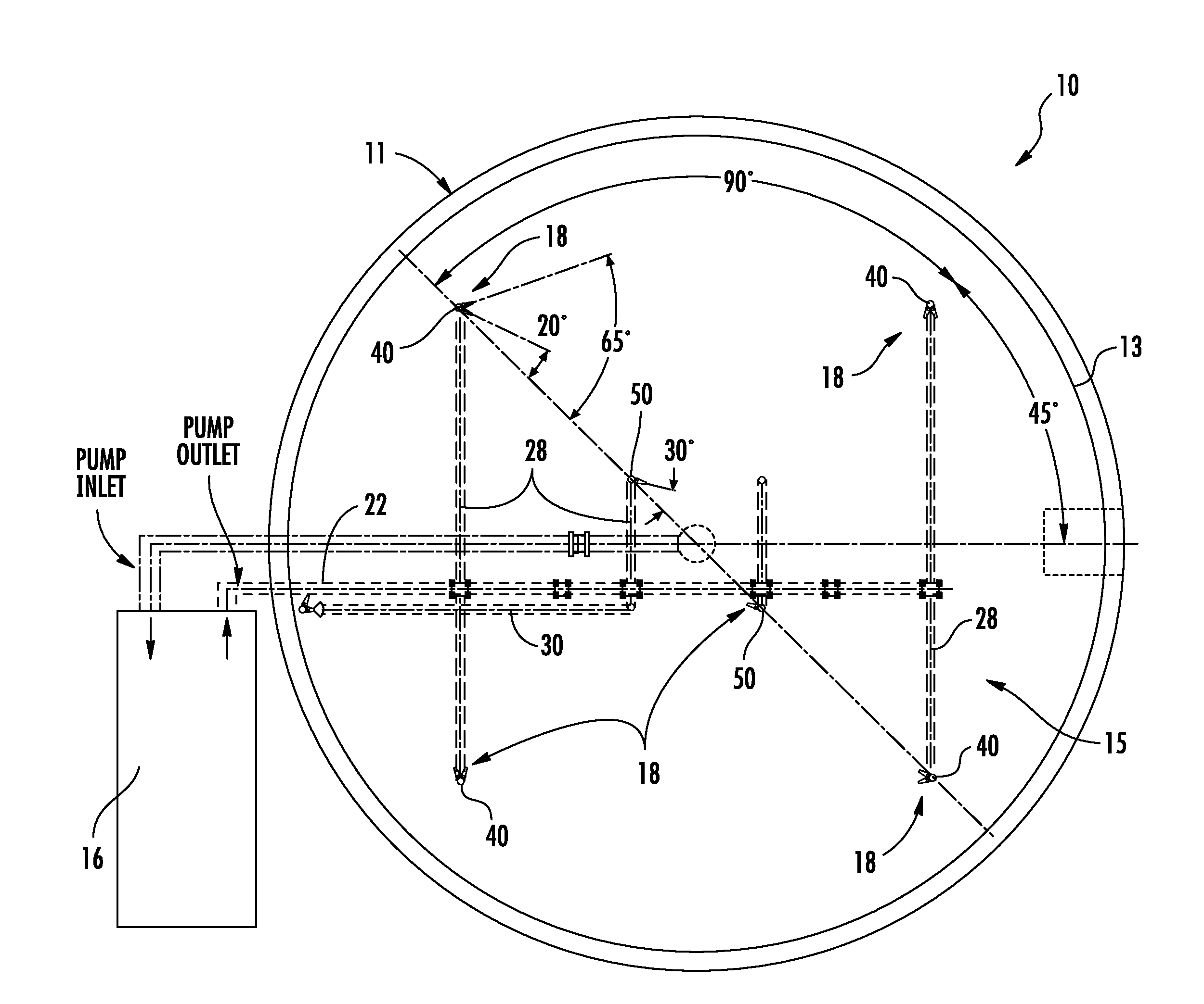
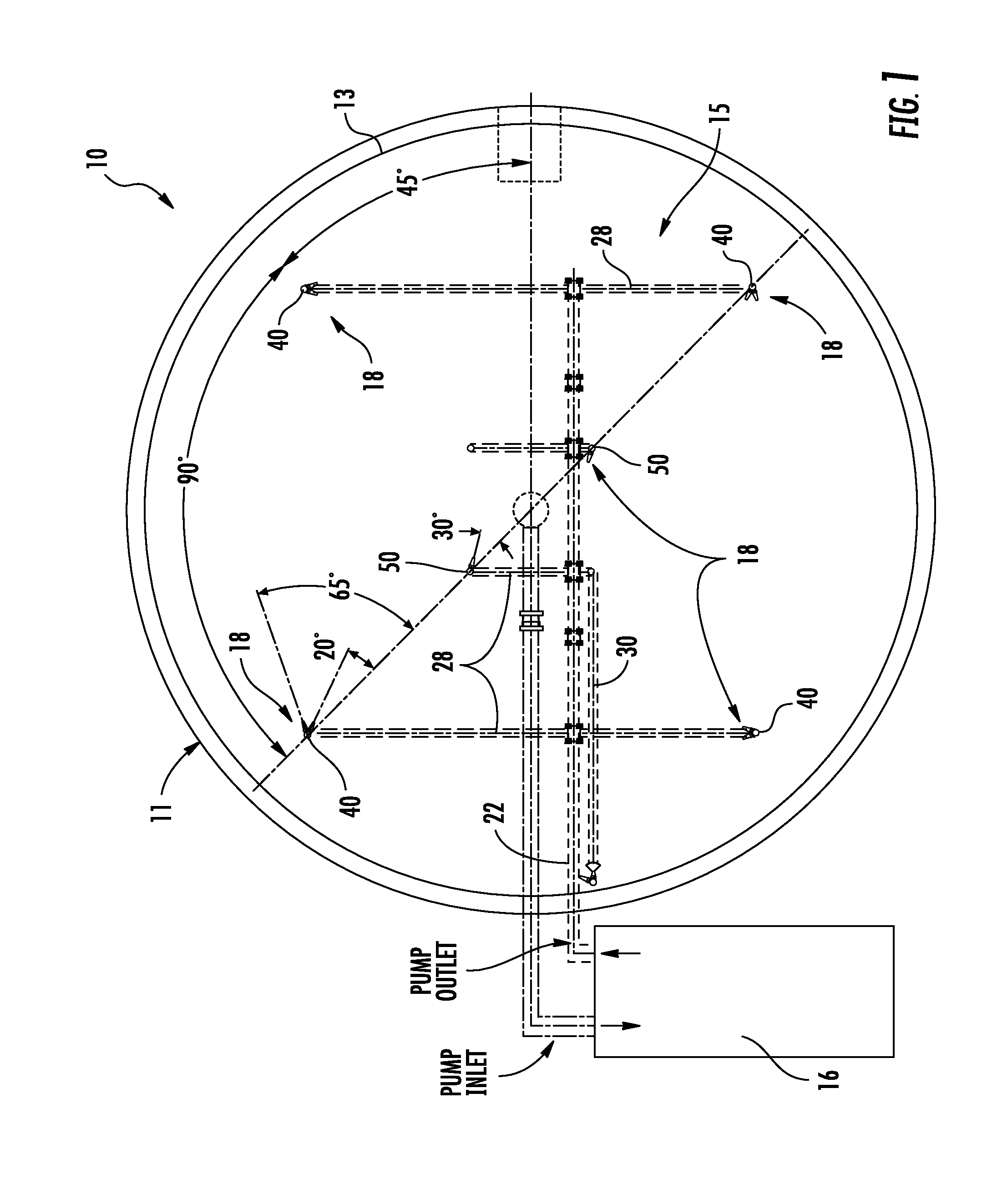
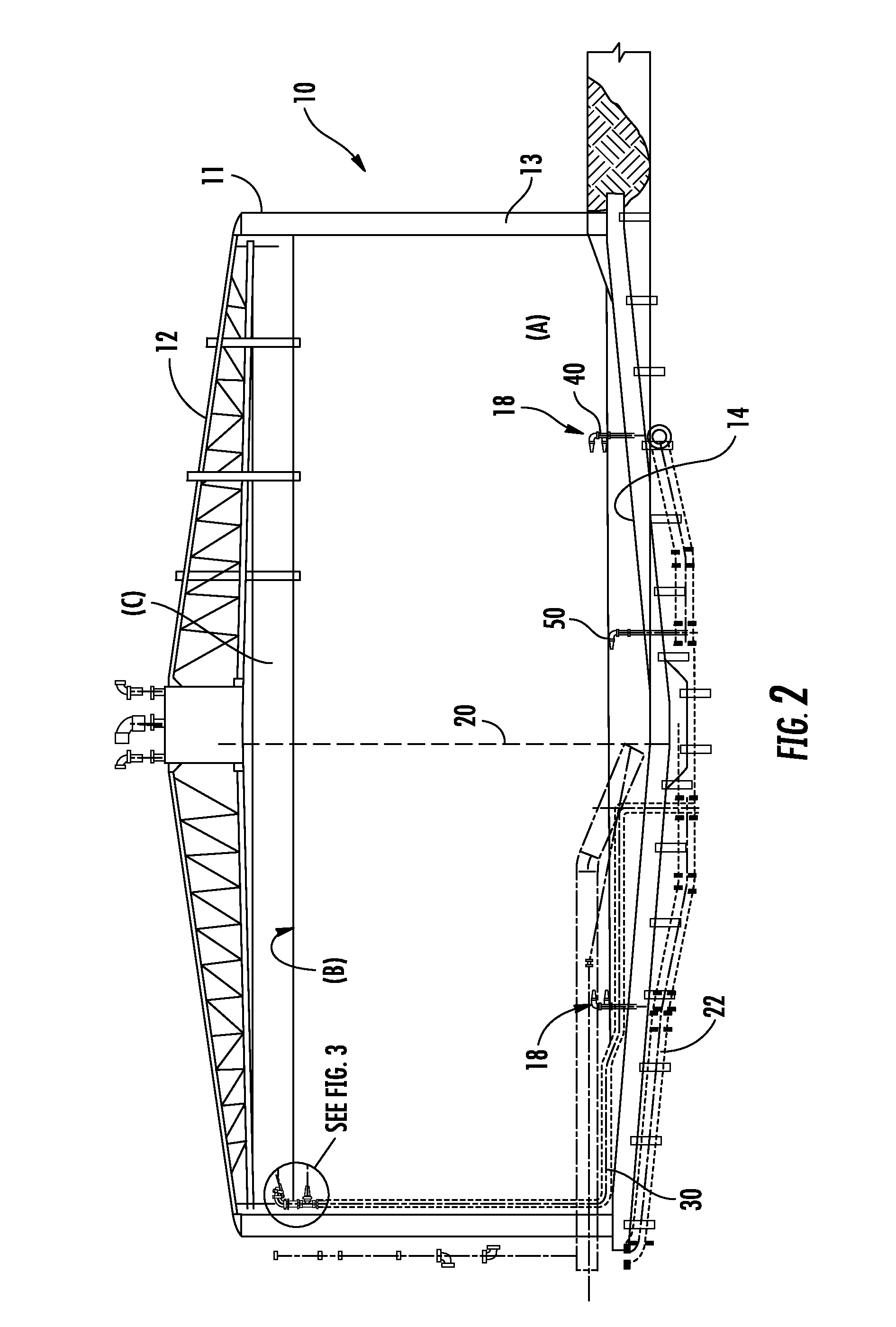
[0021]Referring to FIGS. 1-11, there is illustrated an anti-foaming tank and nozzle system, generally designated by the numeral 10. The described system 10 is discussed with respect to mixing tank contents, which is typically a combination of liquids and solids. More specifically, however, the system 10 is described for use on very large tanks, where mixing at the surface is somewhat diminished, and for use in digesters and the like, wherein a viscous top surface, due to the formation of scum and foam, reduces surface mixing. These particular foaming and scum problems may be found...


PUM

PropertyMeasurementUnit
angle of inclinationaaaaaaaaaa
depthaaaaaaaaaa
depthaaaaaaaaaa

Abstract

A surface foam diffuser system having a first nozzle disposed above a top surface of the at least partially liquid contents, a splash plate positioned adjacent to the first nozzle outlet, and a second nozzle disposed below the top surface of the at least partially liquid contents is disclosed for suppressing foaming in large processing tanks. The system nozzles each have an inlet for receiving pressurized liquid and an outlet for ejecting a liquid stream into the tank, the depth of the second nozzle and the direction of the liquid stream there from being such that rotation of the top surface is facilitated. The spray of the first nozzle, as dispersed by the splash plate, reduces foam on at least a portion of the top surface, with the rotation of the top surface allowing each portion of the top surface to eventually fall within the reducing spray.

Description

TECHNICAL FIELD OF THE INVENTION[0001]The present system relates to a foam busting and sub-surface mixing configuration for use in processing tanks such as, for example, waste-water digesters. Particularly, the present system relates to a unique nozzle arrangement which provides greater foam suppression in sludge-type compositions.BACKGROUND OF THE INVENTION[0002]Surface foaming and sediment deposition can both create problems in storage and treatment tanks where large volumes of liquid / slurry are stored and stirred, mixed, or agitated. In many cases the two problems are inversely related. That is, solving one of the problems may directly worsen the other. This relationship can make it very difficult for those skilled in the art to design and implement a system which addresses and solves both problems.[0003]For example, in activated sludge secondary treatment plants, slurries in large tanks are typically stirred, mixed, or agitated in order to suspend solids in the liquid prior to e...

Claims


Application Information

Patent Timeline
Patent Type & Authority Applications(United States)
IPC IPC(8): B05B1/26
CPCB05B1/267B05B13/0627B05B7/0018B01D19/0047B01D19/02C02F3/1236C02F3/28C02F2301/02C02F2303/12
Inventor DORSCH, GLENN R.KEERAN, KENT H.
Owner VAUGHAN
Why Eureka
Try Eureka