
Controller for a rotating electrical machine

a technology of electrical machines and controllers, which is applied in the direction of dynamo-electric converter control, motor/generator/converter stoppers, polyphase induction motor starters, etc., can solve the problems of large total drive loss, large switching loss, and large loss of driv

Active Publication Date: 2011-07-28
ABB (SCHWEIZ) AG
View PDF12 Cites 20 Cited by
  • Summary
  • Abstract
  • Description
  • Claims
  • Application Information

AI Technical Summary

Benefits of technology

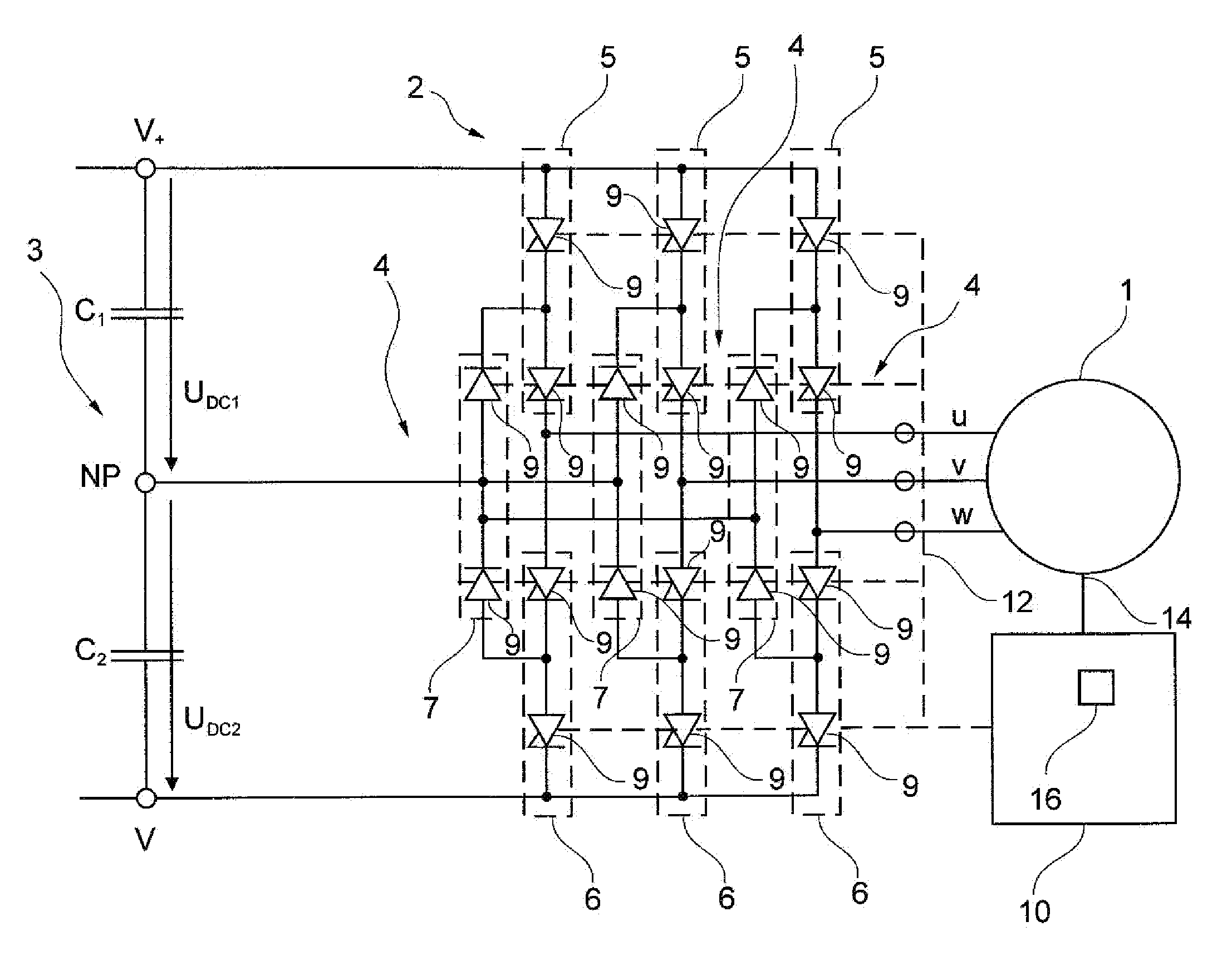
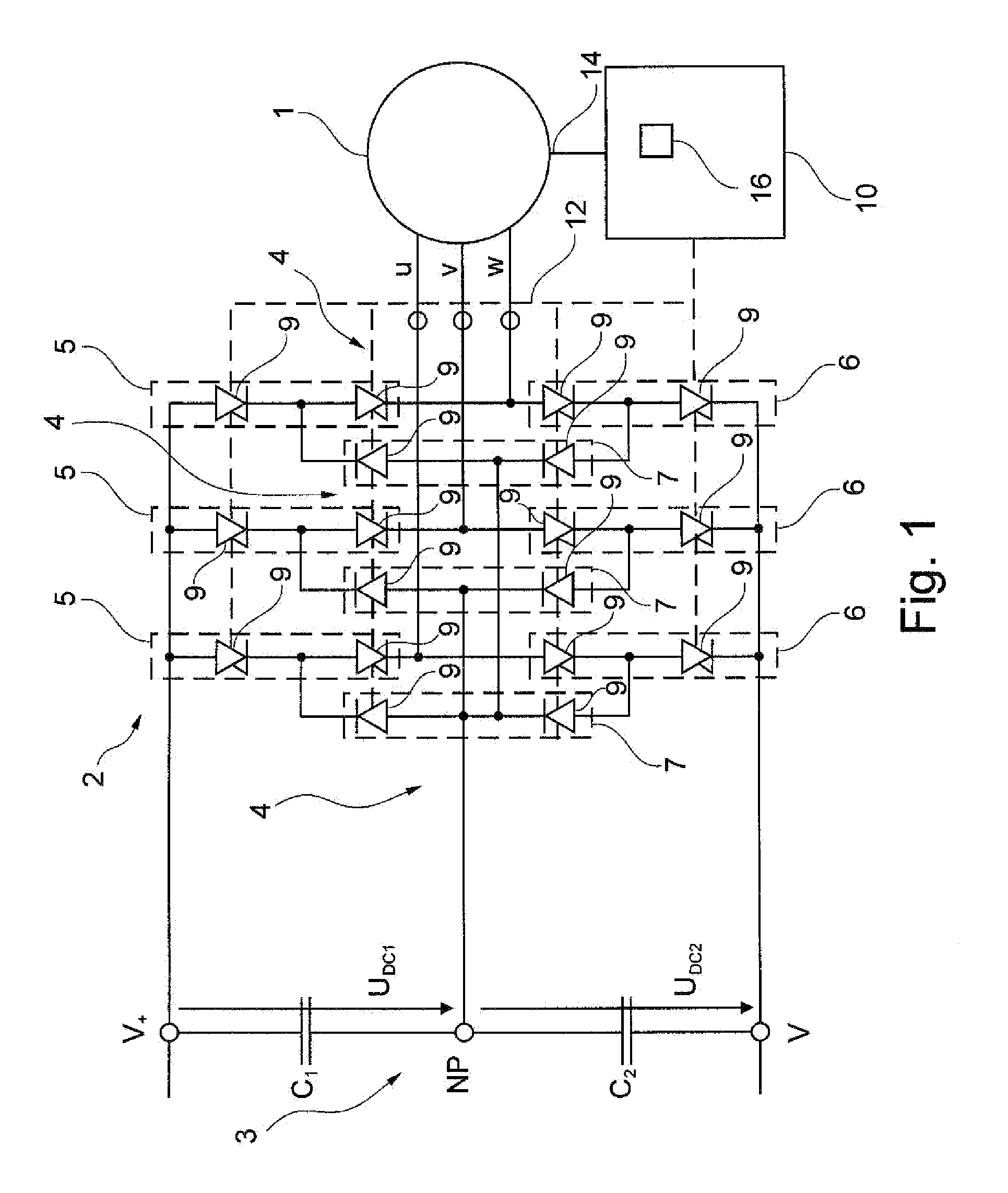
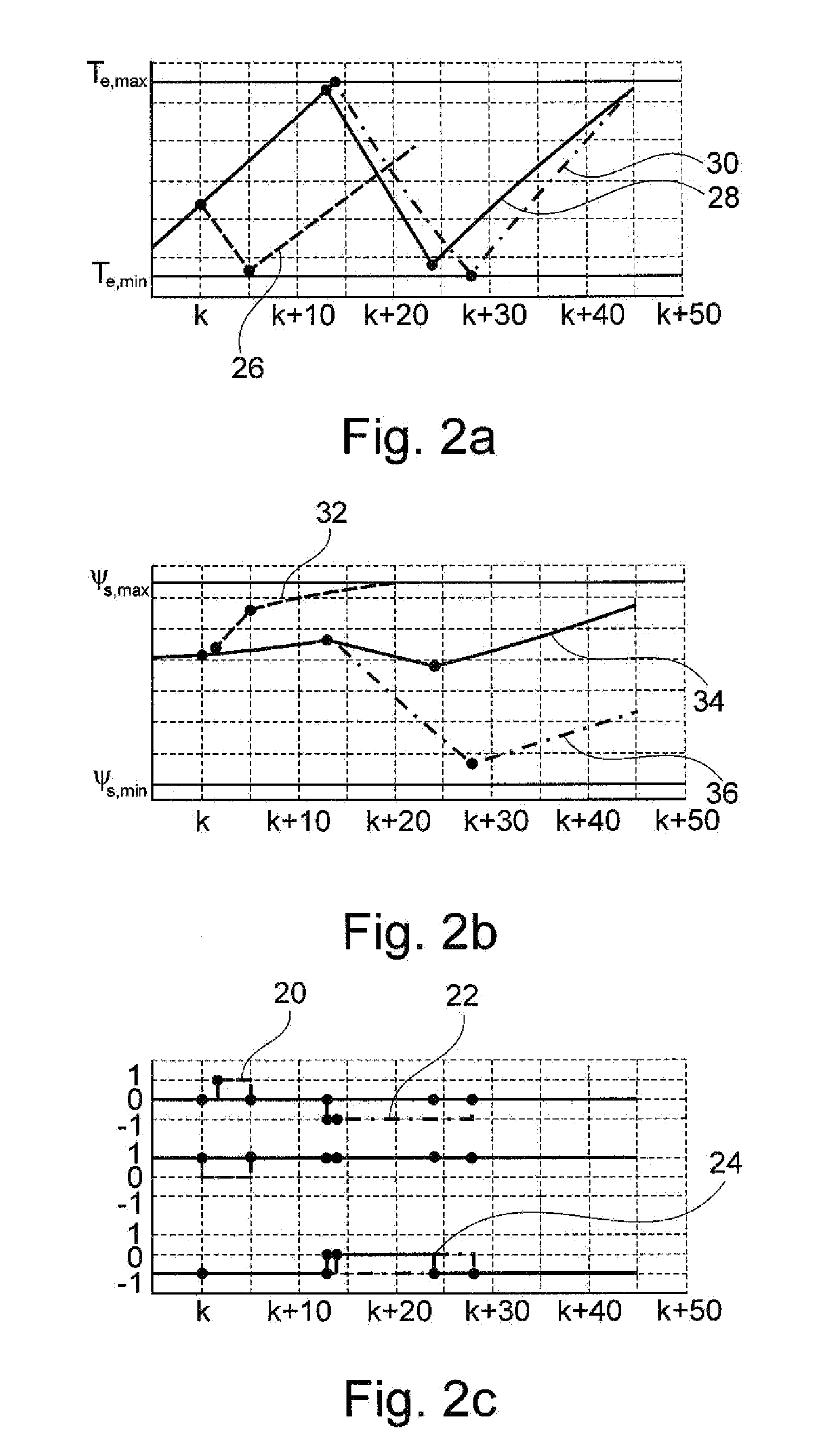
[0007]An exemplary embodiment provides a method for operating a rotating electrical machine. The rotating electrical machine is supplied with electric current by a converter from a DC voltage circuit via at least one phase, and the converter is configured to switch the at least one phase to at least two voltage levels. The exemplary method includes generating switching sequences, wherein each switching sequence includes a series of switching transitions of the converter with a first switching transition. The exemplary method also includes evaluating each of the switching sequences with a quality value, and selecting the switching sequence with a minimum quality value. In addition, the exemplary method includes driving switching elements of the converter with the first switching transition of the selected switching sequence as the selected switching transition, so that at least one phase is switched to a voltage level which corresponds to th

Problems solved by technology

However, the switching losses, which are produced due to semiconductors being switched by the controller and which represent a large proportion or even the majority of the total losses of the drive, can be considerable in the case of DTC.

Method used


Image

  • Controller for a rotating electrical machine
  • Controller for a rotating electrical machine
  • Controller for a rotating electrical machine

Examples


Embodiment Construction

[0025]A reduction in the switching losses can bring about a significant decrease in the operational costs of the drive. Furthermore, such a reduction in the switching losses can result in a more robust and reliable system and can extend the field of application of DTC since reduced switching losses make it possible to operate the same equipment at a higher power.

[0026]Exemplary embodiments of the present disclosure provide electrical drives with reduced operational costs and increased power.

[0027]An exemplary embodiment of the present disclosure provides a method for operating a rotating electrical machine.

[0028]In accordance with an exemplary embodiment of the present disclosure, the rotating electrical machine is supplied with electric current by a converter from a DC voltage circuit via at least one phase. The converter is configured to switch the at least one phase to at least two voltage levels.

[0029]The rotating electrical machine can be an electric motor or an electric drive,...


PUM


Abstract

To minimize switching losses in a rotating electrical machine, exemplary embodiments of the present disclosure proposes an iterative control method which calculates optimal switching states in advance. A rotating electrical machine can be controlled on the basis of this iterative control method.

Description

RELATED APPLICATIONS[0001]This application claims priority under 35 U.S.C. §119 to European Patent Application No. 10151370.3 filed in Europe on Jan. 22, 2010, the entire content of which is hereby incorporated by reference in its entirety.FIELD[0002]This present disclosure relates to the field of operating methods for rotating electrical machines. More particularly, the present disclosure relates to a method for operating a rotating electrical machine, a controller for an electrical converter, a motor system, and a computer-implemented product for operating a rotating electrical machine.BACKGROUND INFORMATION[0003]Direct torque control (DTC) is a method for controlling the torque and the electromagnetic flux in rotating electromagnetic machines and motors, for example, in the medium-voltage range. A typical example of such a controller can be found, for example, in the drive of the ACS 6000 by ABB. Over the last 10 years, DTC has demonstrated a high degree of reliability, robustnes...

Claims


Application Information

Patent Timeline
IPC IPC(8): H02P27/06
CPCH02M7/487H02P27/14H02P27/12H02P23/004H02P23/30H02P27/06H02P23/14
Inventor GEYER, TOBIAS
Owner ABB (SCHWEIZ) AG
Learn More