
Fast Voltage Level Shifter Circuit

a voltage level shifter and circuit technology, applied in logic circuits, pulse automatic control, pulse techniques, etc., can solve the problems of reducing affecting the switching speed and the typical low bandwidth of the common-source amplifier

Active Publication Date: 2011-07-28
SOLAREDGE TECH LTD
View PDF100 Cites 148 Cited by
  • Summary
  • Abstract
  • Description
  • Claims
  • Application Information

AI Technical Summary

Benefits of technology

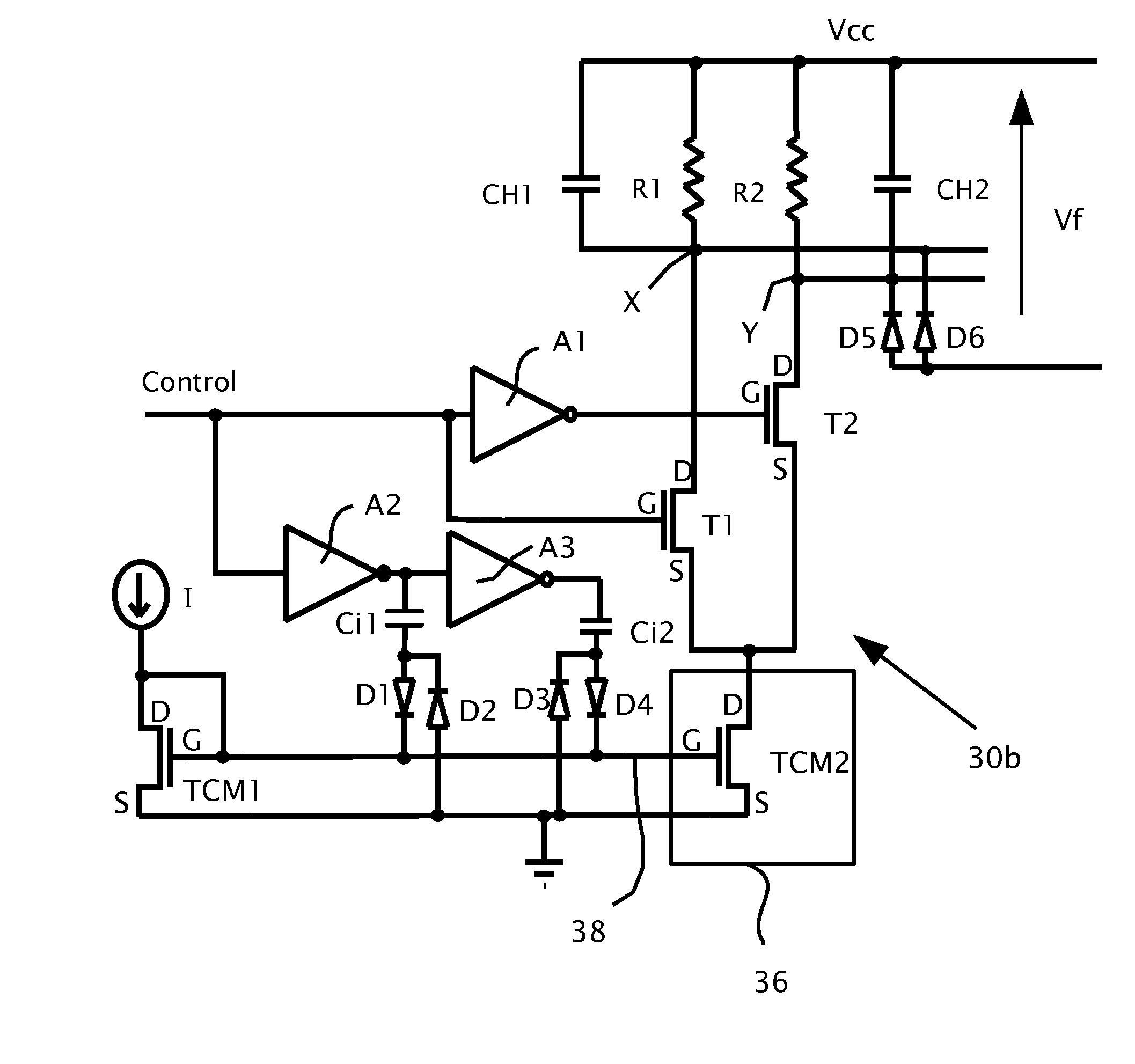
[0021]According to embodiments of the present invention there is provided a voltage level shifting circuit with an input terminal and an output terminal. The level shifting circuit has a switch driven by an input voltage applied to the input terminal to produce an output voltage on the output terminal based on a current drawn through the switch. The switch may be a silicon controlled rectifier (SCR), insulated gate bipolar junction transistor (IGBT), bipolar junction transistor (BJT), field effect transistor (FET), junction field effect transistor (JFET), switching diode, electrical relay, reed relay, solid state relay, insulated gate field effect transistor (IGFET), diode for alternating current (DIAC), or triode for alternating current TRIAC. A current changing mechanism operatively connected to the switch. The current changing mechanism is preferably adapted for changing the current through the switch. The current changing mechanism is typically adapted to change the current when the switch is switched. The current changing mechanism is preferably adapted to provide a current control signal to a leg of the switch.

Problems solved by technology

The bandwidth of the common-source amplifier typically tends to be low, due to high capacitance resulting from the Miller effect.
A low bandwidth due to the effect of Miller capacitance typically reduces switching speed of the common source amplifier.

Method used


Image

  • Fast Voltage Level Shifter Circuit
  • Fast Voltage Level Shifter Circuit
  • Fast Voltage Level Shifter Circuit

Examples


Embodiment Construction

[0031]Reference will now be made in detail to embodiments of the present invention, examples of which are illustrated in the accompanying drawings, wherein like reference numerals refer to the like elements throughout. The embodiments are described below to explain the present invention by referring to the figures.

[0032]Before explaining embodiments of the invention in detail, it is to be understood that the invention is not limited in its application to the details of design and the arrangement of the components set forth in the following description or illustrated in the drawings. The invention is capable of other embodiments or of being practiced or carried out in various ways. Also, it is to be understood that the phraseology and terminology employed herein is for the purpose of description and should not be regarded as limiting.

[0033]By way of introduction, an embodiment of the present invention is directed to allow high current consumption only in the switching time. After the...


PUM


Abstract

A voltage level shifting circuit with an input terminal and an output terminal. The level shifting circuit has a field-effect transistor (FET) switch with a gate attached to the input terminal, a drain attached to the output terminal and a source attached to a current changing mechanism. The current changing mechanism includes a current mirror circuit having an output connected between the source and an electrical earth. The output of the current mirror circuit is preferably adapted to change a current flowing between the drain and the source based on an input voltage applied to the gate.

Description

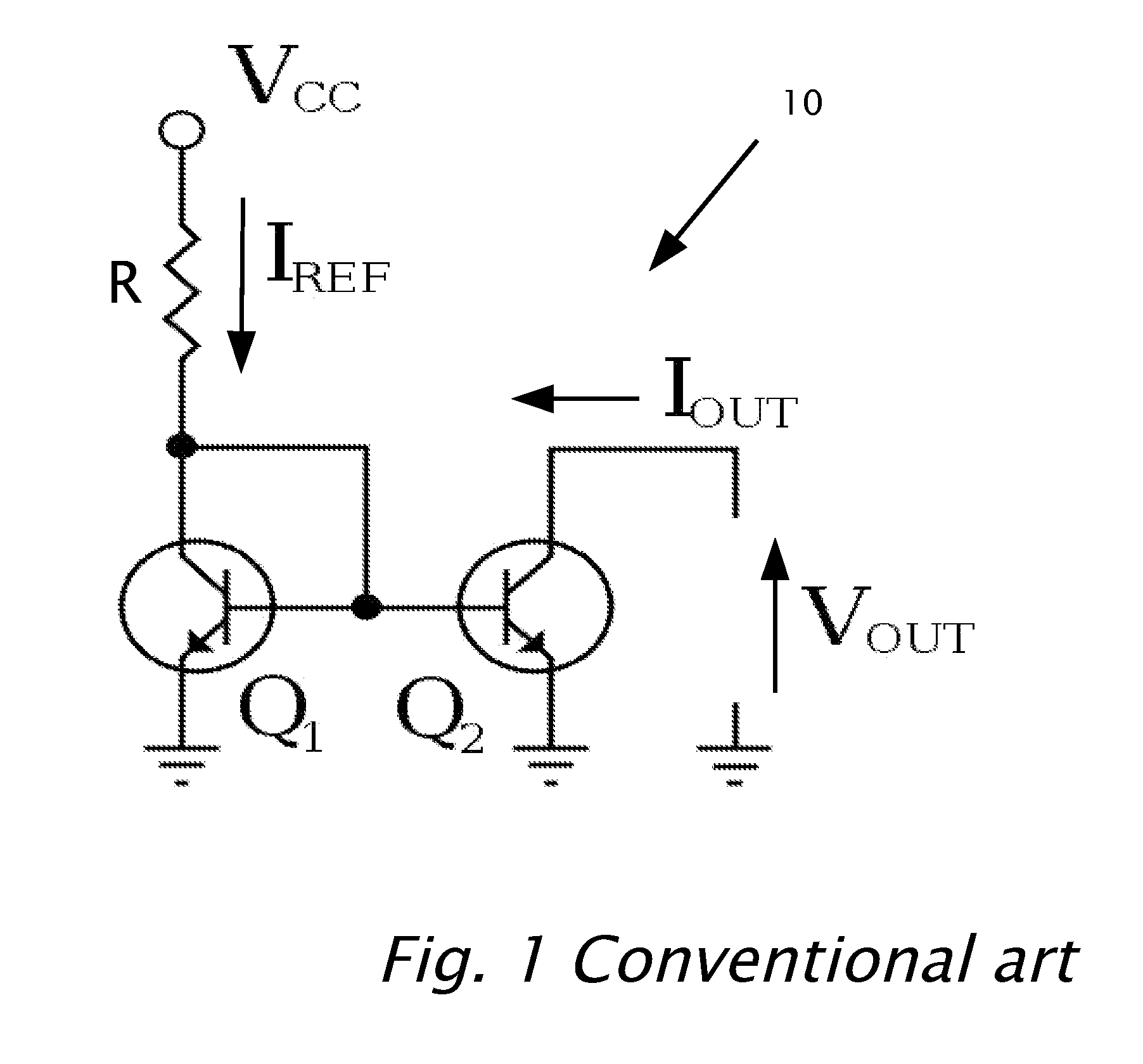
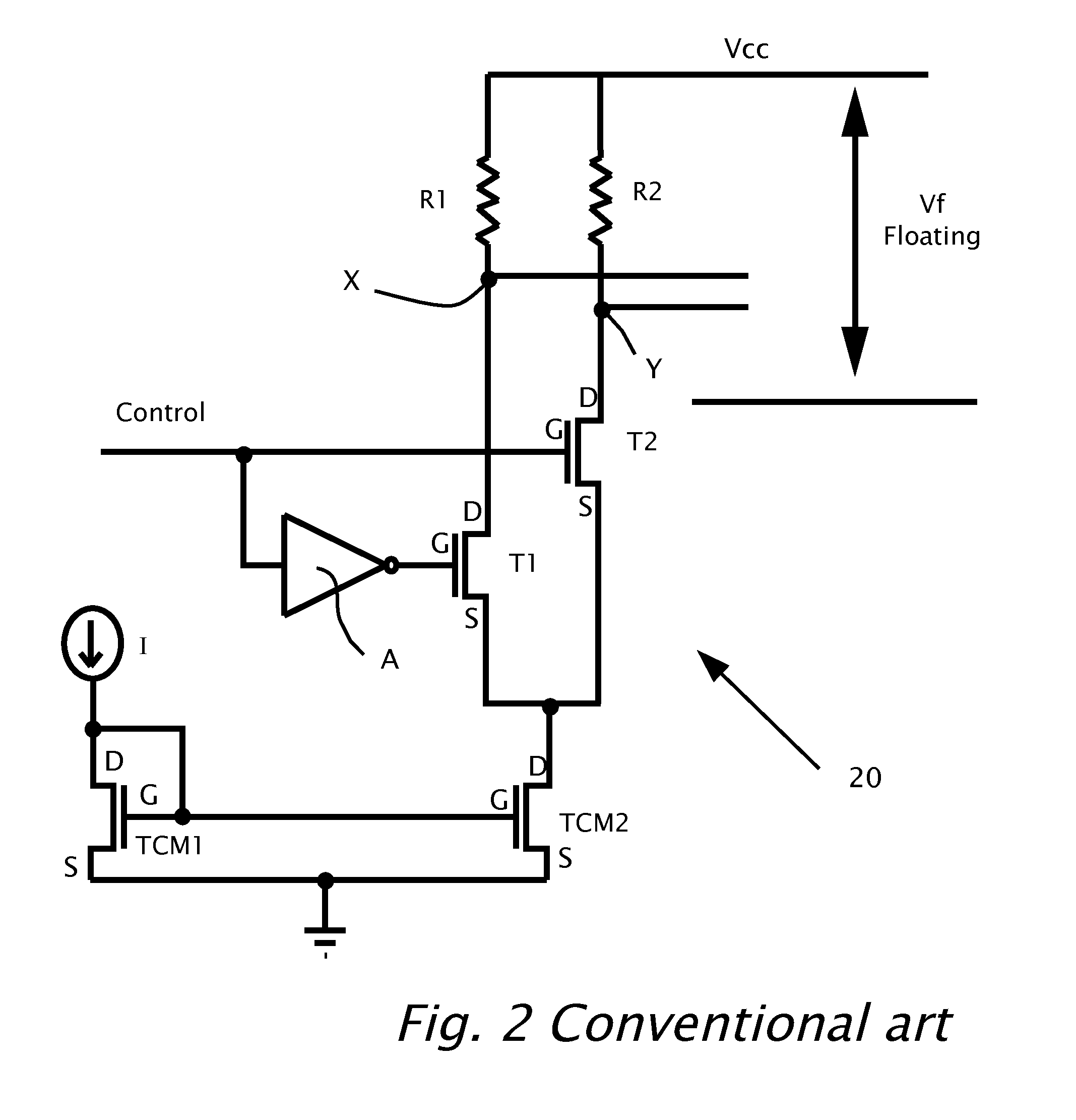
CROSS REFERENCE TO RELATED APPLICATIONS[0001]The present application claims priority from U.S. provisional application No. 61 / 298,555 filed on Jan. 27, 2010 by the present inventor.BACKGROUND[0002]1. Technical Field[0003]The present invention relates to voltage level switching and, more particularly to a voltage level shifter circuit and a method for the operation of the voltage level shifter circuit.[0004]2. Description of Related Art[0005]Reference is now made to FIG. 1 which shows a current mirror circuit 10 according to conventional art. The base of a transistor Q1 is connected to the base of a transistor Q2, along with both of the emitters of Q1 and Q2 typically connected to ground or another common voltage point. A link connects the collector of Q1 to the bases of Q1 and Q2. The collector of Q1 also connects to voltage supply (Vee) via a resistor R. The voltage output (Vout) of current mirror circuit 10 is between the collector of Q2 and ground or between the collector of Q2 a...

Claims


Application Information

Patent Timeline
Patent Type & Authority Applications(United States)
IPC IPC(8): H03L5/00
CPCH03K19/018521H03K19/0185H03K3/356104H03K19/018507H03K3/356
Inventor GAZIT, MEIR
Owner SOLAREDGE TECH LTD
Learn More