System for restoring turbine vane attachment systems in a turbine engine

a technology of turbine engines and attachment systems, which is applied in the field of turbine engines, can solve the problems of negative effect of turbine engine performance, tremendous cost and time savings, and achieve the effect of reducing the restoration process and significant time and cost savings

Active Publication Date: 2011-08-04
SIEMENS ENERGY INC
View PDF40 Cites 12 Cited by
  • Summary
  • Abstract
  • Description
  • Claims
  • Application Information

AI Technical Summary

Benefits of technology

[0006]This invention is directed to a system and method for repairing turbine vane attachment systems in a turbine engine. In at least one embodiment, the invention may be directed to a system and method for repairing wear on diaphragm hook fits configured to attach diaphragm airfoils, which are also referred to as stationary turbine vanes, to a combustion turbine case. The restoration system may be formed from a carriage assembly having an assortment of material processing implements usable to build up material in the worn locations of the turbine vane attachment system in a manner to reestablish a diaphragm hook fit within the specified tolerances. The restoration system may be configured so that the carriage assembly can be positioned within a turbine engine without removing a rotor assembly, thereby resulting in significant time and cost savings. In large scale applications of power generation turbine engines, use of the restoration system can reduce the restoration process by about two weeks.
[0009]The restoration system may be used to repair a turbine vane attachment system, such as a diaphragm hook fit. In at least one embodiment, the restoration system may be used to restore wear regions in conventional diaphragm hook fits that, without restoration, negatively effect performance of the turbine engine. Access to a diaphragm hook fit may first occur by removing a cover half of the combustion turbine case. Once the cover half has been removed, the turbine vanes may be removed using conventional procedures. Removal of the turbine vanes and turbine blades provides sufficient room for the restoration system to be installed in the turbine engine without having to remove the rotor assembly and incur costs of about $500,000. Thus, use of the restoration system to repair a worn region of a turbine vane attachment system results in a tremendous cost and time savings.
[0010]A first generally curved track may be attached to the combustion turbine case proximate to a diaphragm hook fit corresponding to a second row of turbine vanes. A carriage assembly may be movably coupled to the track so that the carriage assembly may travel along the length of the track. Movement of the carriage assembly may be controlled by personnel or by a program on a microcontroller or other appropriate device. The carriage assembly may be placed adjacent to a worn region. A milling cutter may be extended to contact an adjacent worn region, if necessary, to prepare the worn region for repair. The amount of material to be removed may be determined using conventional procedures. A welding head may then be placed in close proximity with the worn region to add material to the worn region to restore the worn region within the specified tolerances of the diaphragm hook fit. The welding head may be passed over a worn region a sufficient number of times to build up the material to a predetermined amount within the specified tolerances of the diaphragm hook fit. The carriage assembly may be moved along the track to facilitate building up material along a length of a worn region. Use of the carriage assembly to add material along the length of a worn region results in a tremendous time savings compared with conventional, manual repair methods.
[0012]An advantage of this invention is that the restoration system and method may be used restore worn regions of a turbine vane attachment system without requiring removal of a rotor assembly. Leaving the rotor assembly in place during the restoration process eliminates about two weeks of work typically required to remove a rotor assembly, thereby saving approximately $500,000 in repair costs per turbine engine.
[0013]Another advantage of this invention is that the restoration system reduces the time necessary to restore a worn region. Many worn regions on turbine vane attachment systems extend along a length of the turbine vane attachment system. The restoration system enables material processing implements to be mechanically controlled and precisely positioned to restore the worn regions in less time than conventional restoration procedures conducted manually.
[0014]Yet another advantage of this invention is that the restoration system enables diaphragm hook fits to be restored more precisely than is capable with conventional, manual restoration procedures.

Problems solved by technology

In at least one embodiment, the restoration system may be used to restore wear regions in conventional diaphragm hook fits that, without restoration, negatively effect performance of the turbine engine.
Thus, use of the restoration system to repair a worn region of a turbine vane attachment system results in a tremendous cost and time savings.

Method used


Image

  • System for restoring turbine vane attachment systems in a turbine engine
  • System for restoring turbine vane attachment systems in a turbine engine
  • System for restoring turbine vane attachment systems in a turbine engine

Examples


Embodiment Construction

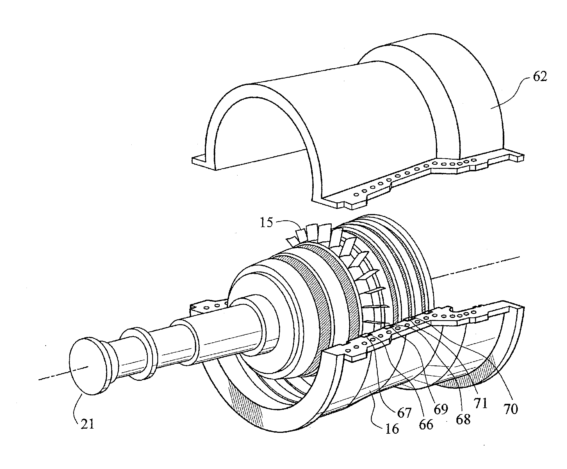
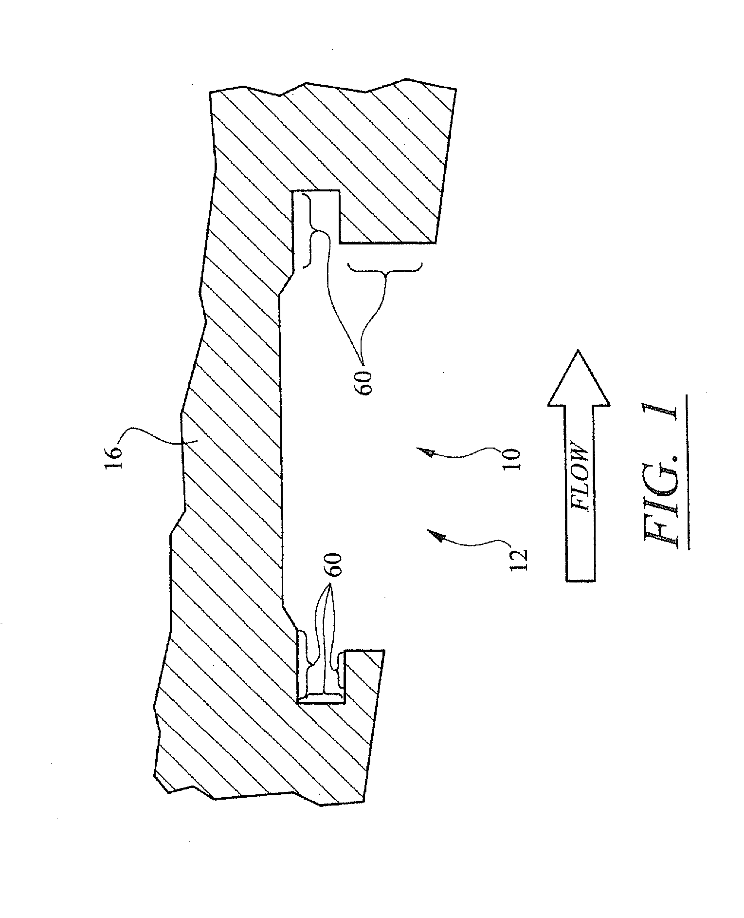
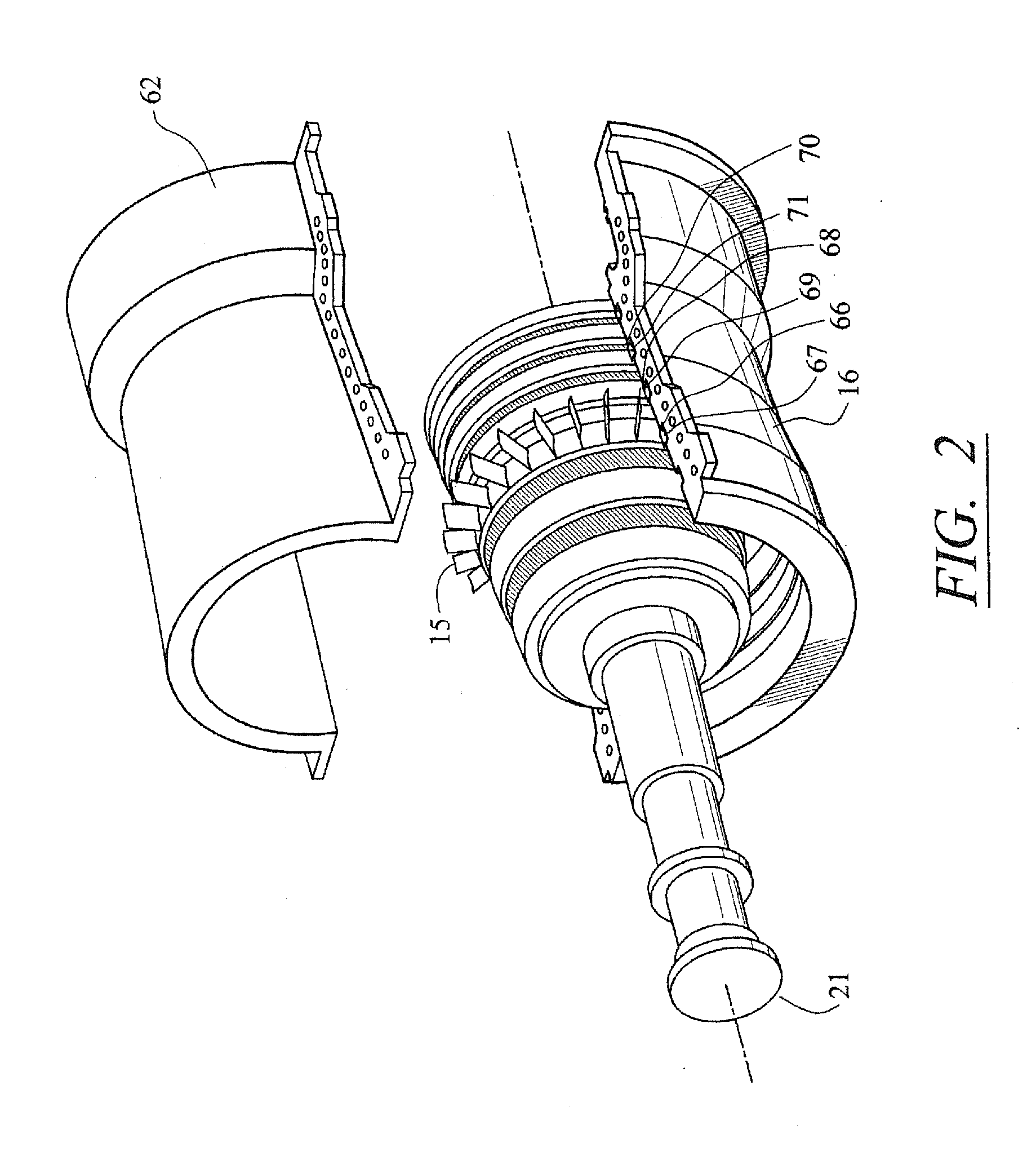
[0025]As shown in FIGS. 2-8, this invention is directed to a system and method for repairing wear on a turbine vane attachment system 10. In at least one embodiment, the invention may be directed to a system and method for repairing wear on a diaphragm hook fit 12 configured to attach diaphragm airfoils 14, which are also referred to as stationary turbine vanes, to a combustion turbine case 16. The restoration system 18 may be formed from a carriage assembly 20 having an assortment of material processing implements 26 usable to build up material in the worn locations of the turbine vane attachment system 10 to return the carriage assembly 20 to its original condition. The restoration system 18 may be configured so that the carriage assembly 20 may be positioned within a combustion turbine case 16 without requiring removal of a rotor assembly 21. Eliminating the need to remove the rotor assembly 21 can reduce the time necessary to repair a turbine vane attachment system by about two ...


PUM

PropertyMeasurementUnit
timeaaaaaaaaaa
heightaaaaaaaaaa
areasaaaaaaaaaa

Abstract

A system and method for repairing turbine vane attachment systems in a turbine engine. In at least one embodiment, the invention may be directed to a system and method for repairing wear on a diaphragm hook fit configured to attach diaphragm airfoils, such as stationary turbine vanes, to a combustion turbine case. The restoration system may be formed from a carriage assembly having an assortment of material processing implements usable to build up material in the worn locations of the turbine vane attachment system to reestablish a diaphragm hook fit within the specified tolerances. The restoration system may be configured so that the restoration process may occur without removing a rotor assembly, which can reduce the repair time by about two weeks. Thus, use of the restoration system can result in a significant time and cost savings.

Description

CROSS-REFERENCE TO RELATED APPLICATION[0001]This application is a divisional of prior U.S. patent application Ser. No. 11 / 243,148, filed Oct. 4, 2005, the entirety of which is incorporated by reference herein.FIELD OF THE INVENTION[0002]This invention is directed generally to turbine engines, and more particularly to turbine vane attachment systems in turbine engines.BACKGROUND[0003]Typically, gas turbine engines include a compressor for compressing air, a combustor for mixing the compressed air with fuel and igniting the mixture, and a turbine blade assembly for producing power. The turbine blade assembly typically includes a rotor assembly rotatable positioned in a turbine combustion case and having a plurality of turbine blades extending radially outward from the rotor assembly. The turbine engine also includes a plurality of stationary turbine vanes, which are also referred to as diaphragm airfoils, extending radially inward from the turbine combustor case. The turbine blades an...

Claims


Application Information

Patent Timeline
Patent Type & Authority Applications(United States)
IPC IPC(8): B23P6/00B23P17/00
CPCB23P6/002F01D5/005F05D2230/80Y10T29/53Y10T29/49318Y10T29/49238Y10T29/49737Y10T29/49734
Inventor BIRD, DEREK
Owner SIEMENS ENERGY INC
Why Eureka
Try Eureka