Radio IC device

a radio ic chip and radiation electrode technology, applied in the direction of burglar alarm mechanical actuation, burglar alarm by hand-portable articles removal, instruments, etc., can solve the problems of reducing the efficiency of transmitting signals from the radio ic chip to the radiation electrode pattern or from the radiation electrode pattern to the radio ic chip, and achieve the effect of reducing the transmission efficiency of signal energy

Active Publication Date: 2011-08-04
MURATA MFG CO LTD
View PDF99 Cites 82 Cited by
  • Summary
  • Abstract
  • Description
  • Claims
  • Application Information

AI Technical Summary

Benefits of technology

[0011]Since a portion of the auxiliary electrode pattern is preferably capacitively coupled to a maximum-voltage section in the radiation electrode pattern, that is, in the vicinity of a location at which the nearly maximum voltage is obtain

Problems solved by technology

However, when the feeder circuit board and the radiation electrode pattern are coupled to each other through a magnetic field or an electric field, when the positional accuracy of mounting the feeder circuit board on the radiation electrode pattern is reduced, a transmission efficiency for signal energy from

Method used


Image

  • Radio IC device
  • Radio IC device
  • Radio IC device

Examples


first preferred embodiment

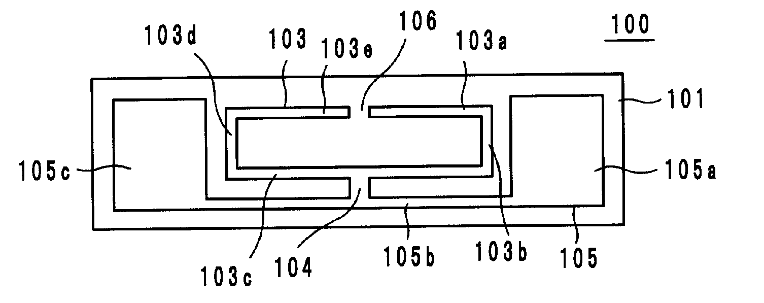
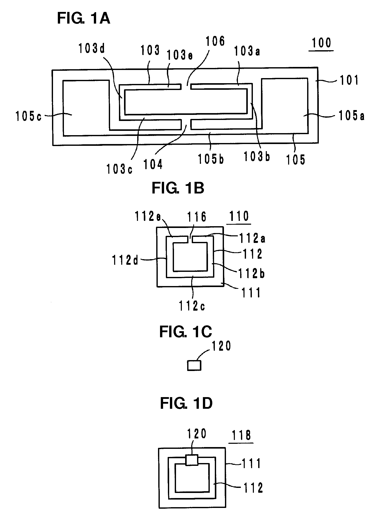
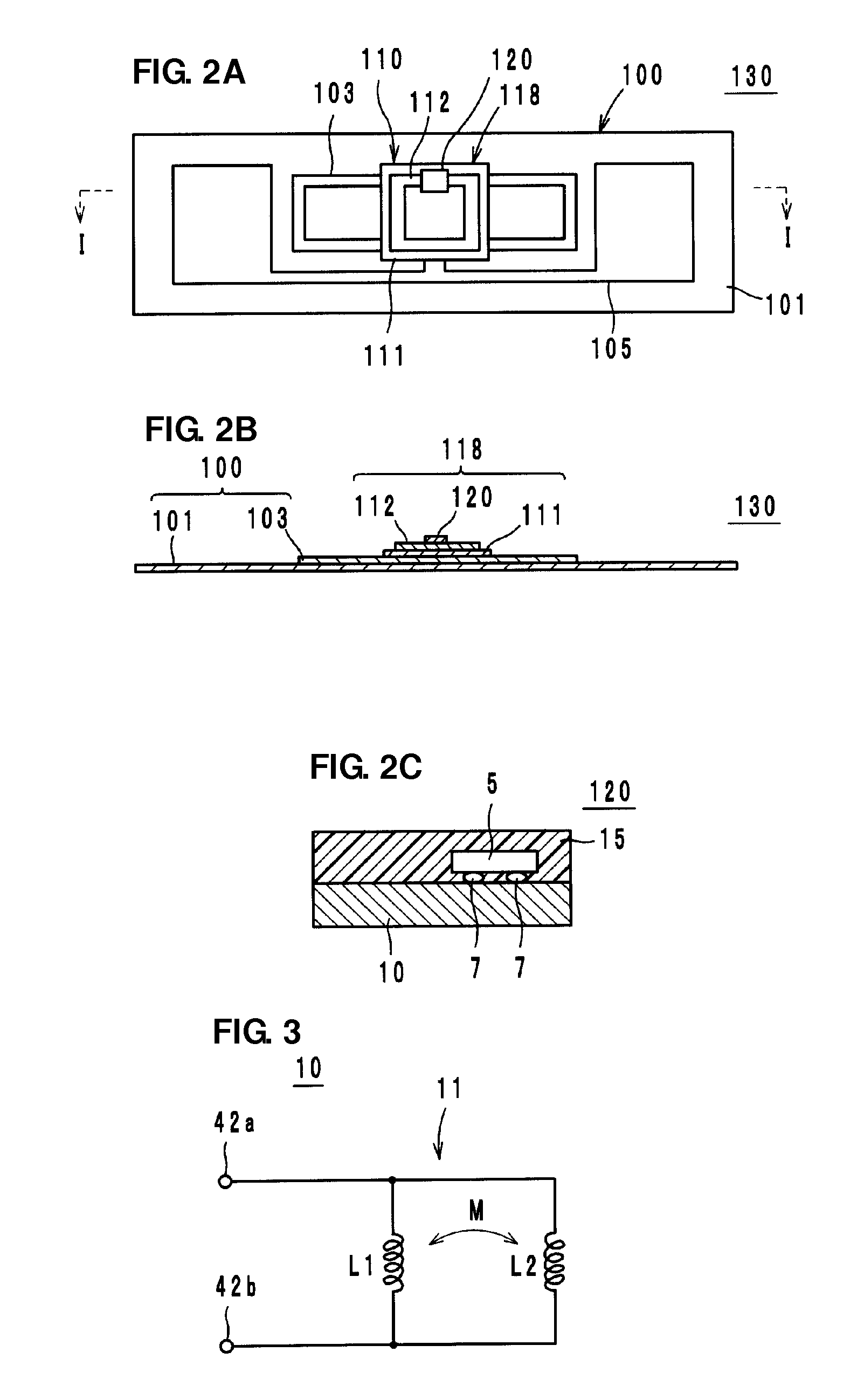
[0032]As illustrated in FIGS. 1A to 1D and FIG. 2, a radio IC device 130 according to a first preferred embodiment of the present invention preferably includes an electromagnetic coupling module 120 including a radio IC chip 5 that processes radio signals, an auxiliary electrode pattern 110 that is connected to the electromagnetic coupling module 120, and a radiation electrode pattern 100 that is coupled to the auxiliary electrode pattern 110 and radiates radio signals.

[0033]As illustrated in FIG. 1A, the radiation electrode pattern 100 is preferably defined by a magnetic field-electric field coupling type antenna pattern in which a magnetic-field radiation electrode 103 having a loop configuration and a predetermined resonant frequency f1 and an electric-field radiation electrode 105 having a dipole configuration and a predetermined resonant frequency f2 are coupled to each other through a coupling section 104, for example. The magnetic-field radiation electrode 103 and the electri...

second preferred embodiment

[0066]As illustrated in FIG. 10, an auxiliary device 210 according to the second preferred embodiment of the present invention is different from the auxiliary device 118 in the first preferred embodiment in that the shape of a loop-shaped electrode 212 that defines an auxiliary electrode pattern 211 is different. That is, the shape of the loop-shaped electrode 212 is not limited to a square shape, and may preferably be a horizontally elongated substantially rectangular shape as in this second preferred embodiment. In addition, the shape of the loop-shaped electrode 212 may preferably be a vertically elongated substantially rectangular shape, a substantially rhomboid shape, a substantially circular shape, or a substantially elliptic shape, for example.

third preferred embodiment

[0067]As illustrated in FIG. 11, an auxiliary device 220 according to the third preferred embodiment of the present invention is different from the auxiliary device 118 in the first preferred embodiment in that the shape of a loop-shaped electrode 213 that defines an auxiliary electrode pattern 211 is different. That is, the shape of the loop-shaped electrode 213 may preferably include a portion thereof that has a meandering shape as in this third preferred embodiment. Note that a capacitor or a resistor may preferably be inserted in series or in parallel into a portion of the loop-shaped electrode. In addition, the loop-shaped electrode may preferably include a layered structure in which coil electrodes are laminated.


PUM


Abstract

A radio IC device that is highly efficient in transmitting signals from a radio IC to a radiation pattern includes a radio IC chip arranged to processes radio signals, an auxiliary electrode pattern that is connected to the radio IC chip and includes a loop-shaped electrode, and a radiation electrode pattern that includes a magnetic-field radiation electrode having a resonant frequency and an electric-field radiation electrode having a resonant frequency. The loop-shaped electrode of the auxiliary electrode pattern is coupled to a maximum-voltage section of the magnetic-field radiation electrode through a capacitor.

Description

BACKGROUND OF THE INVENTION[0001]1. Field of the Invention[0002]The present invention relates to radio IC devices including a radio IC and a radiation electrode pattern, and in particular, to a radio IC device used in an RFID (Radio Frequency Identification) system.[0003]2. Description of the Related Art[0004]In recent years, RFID systems, in which a reader / writer that generates an induction field and an IC tag (hereinafter referred to as a radio IC device) that is attached to an article and stores predetermined information communicate with each other by a non-contact method using an electromagnetic field to transmit the predetermined information, have been developed as an article management system.[0005]Radio IC devices used in such an RFID system include a radio IC chip that processes a predetermined radio signal and a radiation electrode pattern that performs transmission and reception of the radio signal, and a known radio IC device is described in, for example, International Pa...

Claims


Application Information

Patent Timeline
IPC IPC(8): G06K19/077H01Q5/10
CPCG06K19/07749H01Q1/38H01Q1/2225H01L2924/181H01L2224/16225H01L2924/00012
Inventor KATO, NOBORUIKEMOTO, NOBUO
Owner MURATA MFG CO LTD
Why Eureka
Try Eureka