Broadband optics for manipulating light beams and images

a light beam and optics technology, applied in optics, instruments, diffraction gratings, etc., can solve the problems of reduced overall transmission of the system, large bulky and heavy, and complex opto-mechanical systems

Inactive Publication Date: 2011-08-04
UNITED STATES OF AMERICA THE AS REPRESENTED BY THE SEC OF THE ARMY
View PDF0 Cites 153 Cited by
  • Summary
  • Abstract
  • Description
  • Claims
  • Application Information

AI Technical Summary

Benefits of technology

The second objective of the present invention is incorporating in said set DWs with controlled characteristics of their optical properties for further enhancing optical manipulation capabilities of said systems.

Problems solved by technology

These opto-mechanical systems are complex, bulky and heavy for large area beams.
They are relatively slow and have limited range of angles that could be covered within given time period.
As a result, the overall transmission of these systems is reduced along with their radiation damage threshold, and their speed is limited by the liquid crystal spatial light modulators and variable retarders.
The problem with such systems is that phase gratings typically diffract light into multiple orders that need to be blocked along with the order beam.
Blazed gratings such as proposed in the U.S. Pat. No. 6,792,028 to Cook et al., still exhibit a multitude of diffraction orders due to their discontinuous structure and do not improve considerably on angular selectivity and efficiency.

Method used


Image

  • Broadband optics for manipulating light beams and images
  • Broadband optics for manipulating light beams and images
  • Broadband optics for manipulating light beams and images

Examples


Embodiment Construction

Before explaining the disclosed embodiment of the present invention in detail it is to be understood that the invention is not limited in its application to the details of the particular arrangement shown since the invention is capable of other embodiments. Also, the terminology used herein is for the purpose of description and not limitation.

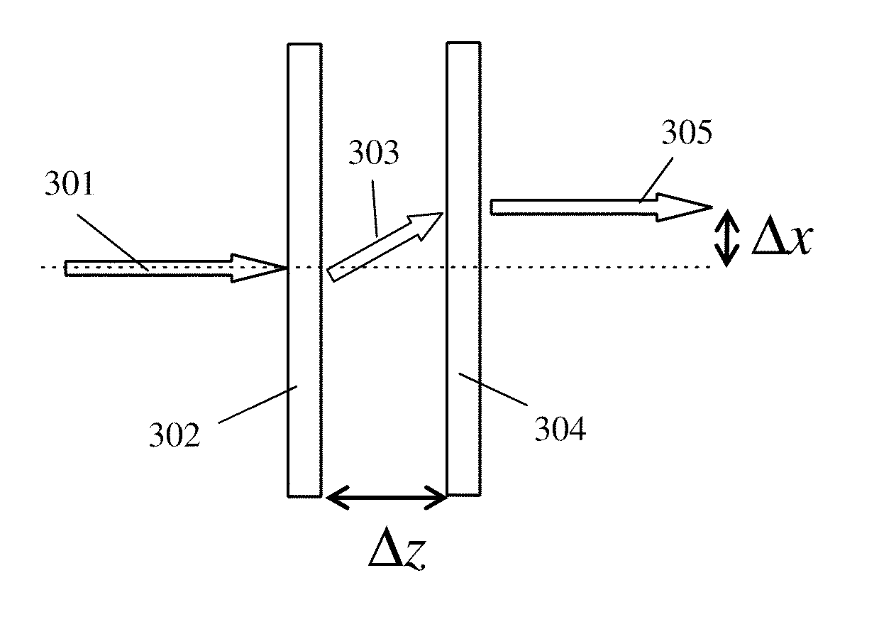
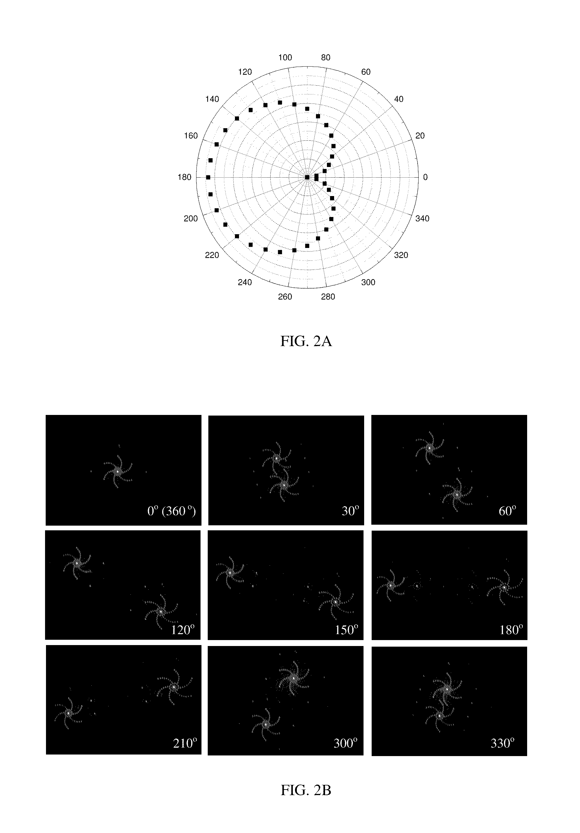
The preferred embodiment of the present invention includes two DWs, marked with numerals 103 and 105 in FIG. 1A, arranged parallel to each other in close proximity. At the output of the system of DWs 103 and 105, the pointing direction of the light beam 108, circularly polarized as shown by spirals 102 and 107, is, in general, different from that of the propagation direction of the light beam 101 incident on the system, controlled with relative rotational positions of the DWs as schematically shown by arrows 104 and 106. The optical axis orientation pattern corresponding to different rotational positions of said DWs is shown in FIG. 1B wherein ...


PUM


Abstract

The objective of the present invention is providing optical systems for controlling with propagation of light beams in lateral and angular space, and through optical apertures. Said light beams include laser beams as well as beams with wide spectrum of wavelengths and large divergence angles. Said optical systems are based on combination of diffractive waveplates with diffractive properties that can be controlled with the aid of external stimuli such as electrical fields, temperature, optical beams and mechanical means.

Description

CROSS REFERENCES[1] S. R. Nersisyan, N. V. Tabiryan, D. M. Steeves, B. R. Kimball, “Optical Axis Gratings in Liquid Crystals and their use for Polarization insensitive optical switching,” J. Nonlinear Opt. Phys. & Mat., 18, 1-47 (2009).[2] P. F. McManamon, P. J. Bos, M. J. Escuti, J. Heikenfeld, S. Serati, H. Xie, E. A. Watson, A Review of Phased Array Steering for Narrow-Band Electrooptical Systems, Proceedings of the IEEE, 97, pp. 1078-1096, 2009.[3] S. R. Nersisyan, N. V. Tabiryan, L. Hoke, D. M. Steeves, B. Kimball, Polarization insensitive imaging through polarization gratings, Optics Express, 17 (3), 1817-1830, 2009.[4] C. Oh, J. Kim, J. F. Muth, M. Escuti, A new beam steering concept: Riesley gratings, Proc. SPIE, vol. 7466, pp. 74660J1-J8, 2009.[5] J. C. Wyant, Rotating diffraction grating laser beam scanner, Applied Optics, 14, 1057-1058, 1975.U.S. Patent Documents7,319,566January 2008Prince et al.7,324,286January 2008Glebov et al.6,792,028September 2004Cook et al.3,721,486...

Claims


Application Information

Patent Timeline
Patent Type & Authority Applications(United States)
IPC IPC(8): G02B27/44
CPCG02B5/1828G02B27/44G02B27/0944G02B27/425G02B26/0808G02B27/4261G02B27/42G02B5/3083G02B5/1866G02B27/4272
Inventor TABIRIAN, NELSONNERSISYAN, SARIKKIMBALL, BRIANSTEEVES, DIANE
Owner UNITED STATES OF AMERICA THE AS REPRESENTED BY THE SEC OF THE ARMY
Why Eureka
Try Eureka