
Measuring device with a reduced share of stray light

a technology of stray light and measuring device, which is applied in the direction of distance measurement, instruments, lenses, etc., can solve the problems of affecting the quality of measured data, impairing the ratio of usable light to stray light, etc., and achieve the effect of reducing the share of stray light incident and improving the dynamic range of the devi

Active Publication Date: 2011-08-04
TRIMBLE JENA
View PDF12 Cites 42 Cited by
  • Summary
  • Abstract
  • Description
  • Claims
  • Application Information

AI Technical Summary

Benefits of technology

[0008]Therefore, it is desirable to further improve the dynamic range for a device to measure using a light beam. Especially it is desirable, in a device for measuring by means of a light beam to reduce the share of stray light incident on the receiver which is generated within the device.

Problems solved by technology

Due to placement of the prism in the optical path of the lens array and because the prism is designed to be small, to permit as much measurement light as possible to be incident on the receiver, especially when the measurement light is coupled into the optical path through the mirror or prism, crosstalk effects result, which impair the quality of the measured result.
Stray light or reflected light generated in the measuring device by the light beam can be incident on the receiver as stray light, and impair the ratio of usable light to stray light.

Method used


Image

  • Measuring device with a reduced share of stray light
  • Measuring device with a reduced share of stray light
  • Measuring device with a reduced share of stray light

Examples


Embodiment Construction

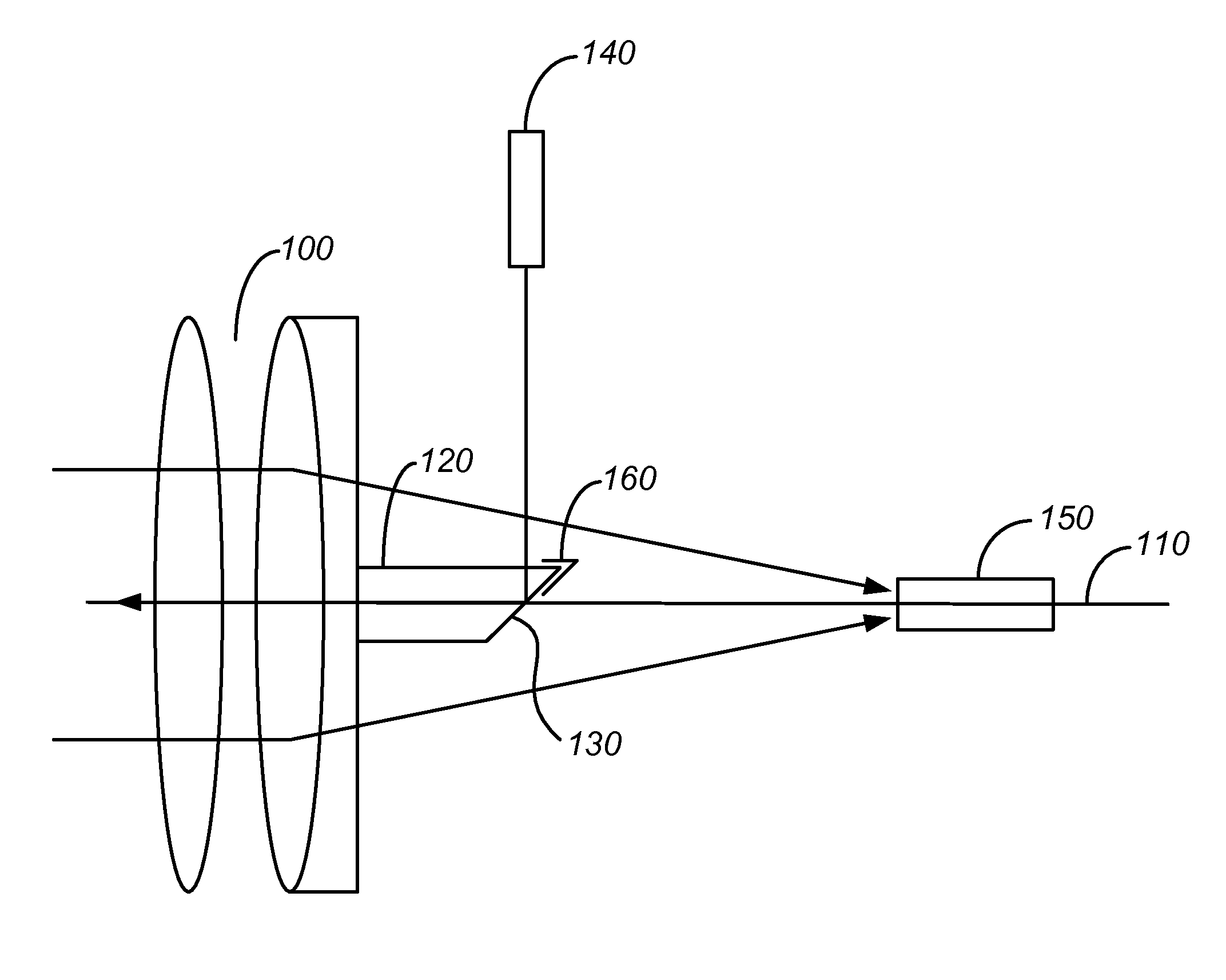
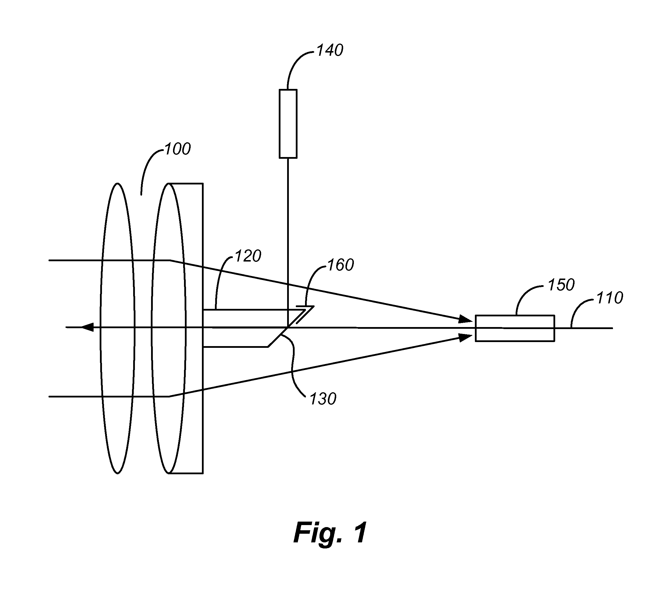
[0017]FIG. 1 shows a schematic arrangement of a device for measurement by means of a light ray according to one embodiment form.

[0018]Generally, for example, the device can be used in measurement or surveying devices with a telescope or camera as a distance measuring device. Light to measure, for example, the distance to an object is coupled to the optical axis and measurement light reflected from the object is detected and evaluated by the receiver. Very generally the device can however be used to measure by means of a light ray, in every optical device in which an optical telescope is used for measurement coaxial to a light ray. A laser source or another light source can be used as the light source.

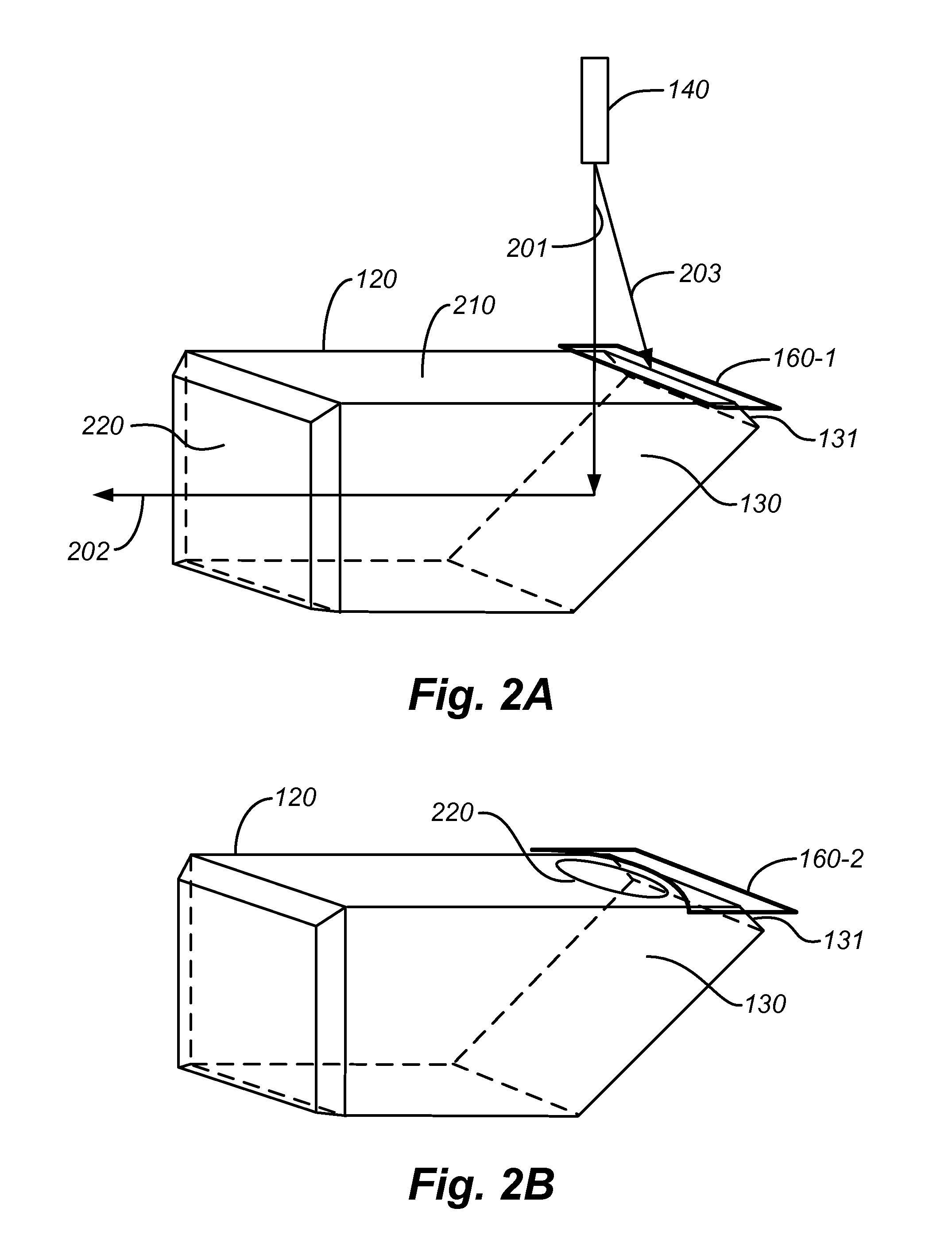
[0019]The device for measuring by means of a light ray as per the present embodiment form comprises an array of lenses 100 along an optical axis 110, a prism 120 placed on one of the lenses with a slanted surface 130 for coupling the light ray incident from a light source 140 lateral to...


PUM

PropertyMeasurementUnit
areaaaaaaaaaaa
thicknessaaaaaaaaaa
distanceaaaaaaaaaa

Abstract

A device for measurement by means of a light ray is equipped with a covering device for reducing stray light. The device comprises an array of lenses along an optical axis; a prism attached to one of the lenses with a slanted surface for coupling of the light ray incident from a light source placed lateral to the optical axis, onto the optical axis, so that the light ray can pass through the array of lenses along the optical axis; a receiver for receipt of a share of the light ray reflected by an object; and a covering device for at least one area of the prism that scatters a share of the light ray as stray light to the receiver.

Description

CROSS-REFERENCES TO RELATED APPLICATIONS[0001]The present application claims priority to German Patent Application No. 10 2009 028 861.9, filed Aug. 25, 2009, entitled “MEASURING DEVICE WITH A REDUCED SHARE OF STRAY LIGHT,” the disclosure of which is hereby incorporated by reference in its entirety.BACKGROUND OF THE INVENTION[0002]The present invention relates to a device for measuring by means of light rays, for example a distance-measuring device, with a reduced share of stray light.[0003]Measuring devices that use a light ray, such as laser beams, to for example measure the distance between the measuring device and an object of interest, are well known. In such devices a light beam is sent in the visible or invisible range, such as a laser beam, through a lens array and a share of the light beam reflected by the object passes through the lens array again and is received by a detector of the measuring device. From the received signal, the distance of the measuring device to the ob...

Claims


Application Information

Patent Timeline
Patent Type & Authority Applications(United States)
IPC IPC(8): G02B5/04
CPCG01S7/4812G02B5/04Y10T29/49828G02B3/0006G01C3/02G02B7/1805
Inventor GORING, HERMANNVOGEL, MICHAEL
Owner TRIMBLE JENA
Learn More