Picture signal conversion system

a technology of picture signal and conversion system, which is applied in the field of picture signal conversion system, can solve problems such as deteriorating resolution

Inactive Publication Date: 2011-08-04
JAPAN SCI & TECH CORP
View PDF6 Cites 17 Cited by
  • Summary
  • Abstract
  • Description
  • Claims
  • Application Information

AI Technical Summary

Benefits of technology

[0026]It is desirable to provide a picture signal conversion system having a filtering function of removing noise from the video signal to yield a clear picture with emphasized edges.
[0027]It is desirable to provide a picture signal conversion system that allows a clear picture performing a smooth motion to be displayed and that has the moving picture processing function effective for contents communication or for picture retrieval.

Problems solved by technology

It is noted that the resolution is deteriorated by the interlaced scanning.

Method used


Image

  • Picture signal conversion system
  • Picture signal conversion system
  • Picture signal conversion system

Examples


Embodiment Construction

[0075]Preferred embodiments of the present invention will now be described with reference to the drawings. It should be noted that the present invention is not to be limited to the embodiments as now described and may be altered as appropriate within the range not departing from the scope of the invention.

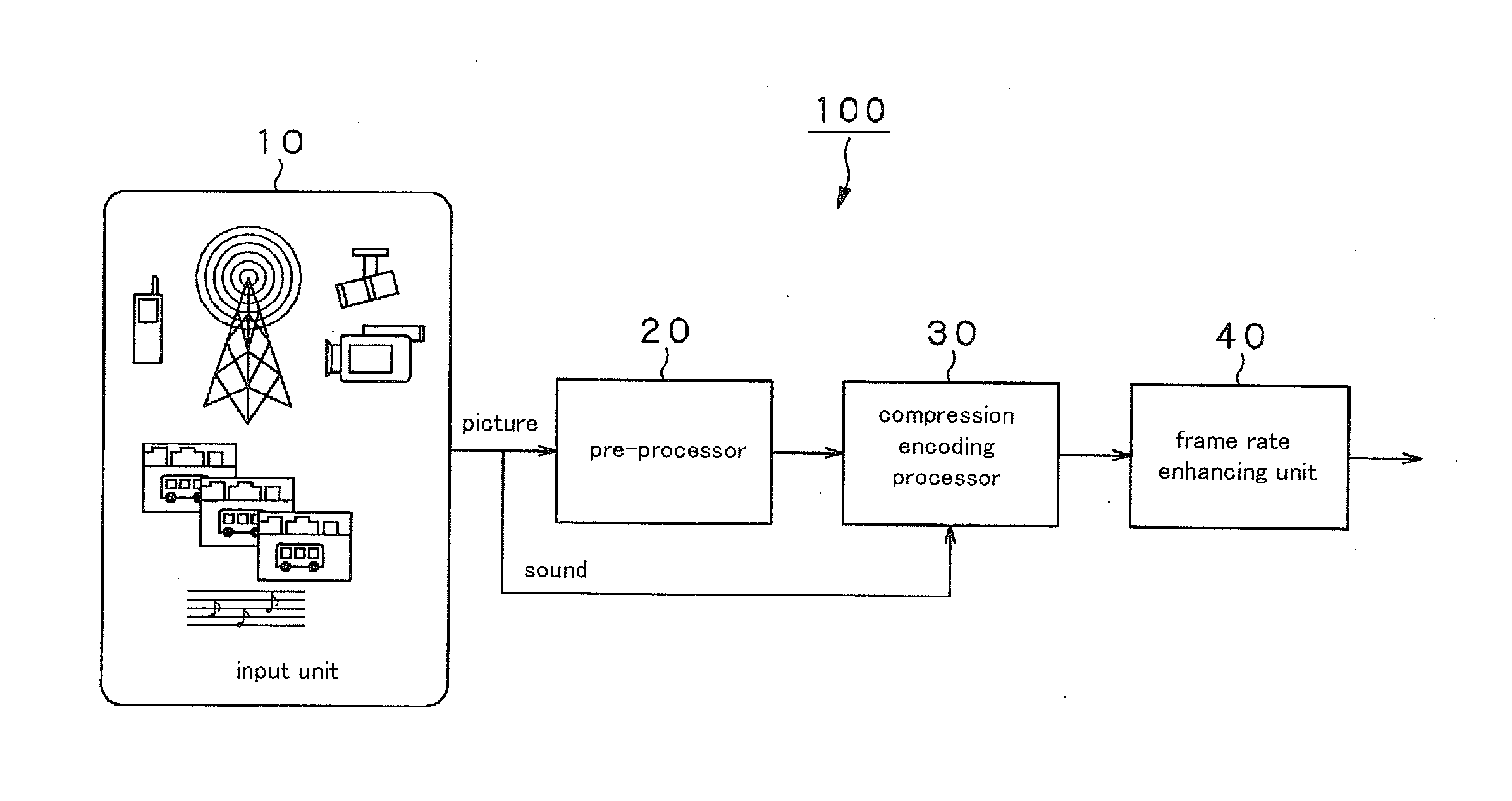
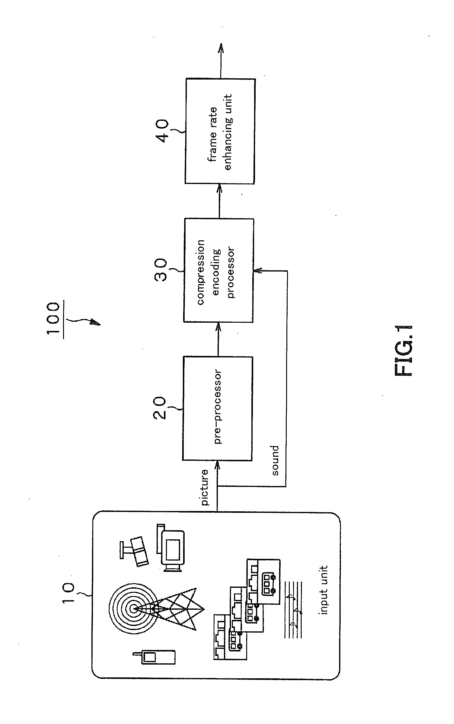
[0076]The present invention is applied to a picture signal conversion system 100, configured as shown for example in FIG. 1 .

[0077]The picture signal conversion system 100 includes a pre-processor 20 that removes noise from the picture information entered from a picture input unit 10, such as an image pickup device, a compression encoding processor 30 and a frame rate enhancing unit 40. The compression encoding processor 30 inputs the picture information freed of noise by the pre-processor 20 and encodes the input picture information by way of compression. The frame rate enhancing unit 40 enhances the frame rate of the picture information encoded for compression by the compression ...


PUM


Abstract

A reverse filter operates for adding noise n(x,y) to an output of a deteriorated model of a blurring function H(x,y) to output an observed model g(x,y). The blurring function inputs a true picture f(x,y) to output a deteriorated picture. The reverse filter recursively optimizes the blurring function H(x,y) so that the input picture signal will be coincident with the observed picture. In this manner, the reverse filter extracts a true picture signal. A corresponding point is estimated, based on a fluency theory, on the true input picture signal freed of noise contained in it by the reverse filter (20). The motion information of a picture is expressed in the form of a function. A plurality of signal spaces is selected by an encoder for compression (30) for the input picture signal. The picture information is expressed by a function from one selected signal space to another. The motion information of the picture expressed by the function and the signal-space-based picture information expressed in the form of a function are expressed in a preset form to encode the picture signal by compression. The picture signal encoded for compression has its frame rate enhanced by a frame rate enhancing processor (40).

Description

TECHNICAL FIELD[0001]This invention relates to a picture signal conversion system that converts a moving picture into the picture information higher in resolution.[0002]The present Application claims priority rights based on Japanese Patent Applications 2008-227628, 2008-227629 and 2008-227630, filed in Japan on Sep. 4, 2008. These applications of the senior filing date are to be incorporated by reference in the present application.BACKGROUND ART[0003]In these days, marked progress has been made in the techniques of digital signals in the multi-media industry or IT (Information Technology) industry, especially the techniques of communication, broadcasting, recording mediums, such as CD (Compact Disc), DVD (Digital Versatile Disc), medical or printing applications handling moving pictures, still pictures or voice. Signal encoding for compression, aimed to decrease the volume of the information, represents a crucial part of the digital signal techniques handling the moving pictures, s...

Claims


Application Information

Patent Timeline
Patent Type & Authority Applications(United States)
IPC IPC(8): H04N7/64H04N7/26H04N19/89
CPCG06T5/002G06T7/2013G06T2207/10016H04N19/521H04N7/0127H04N19/537H04N19/577H04N7/0117G06T7/223
Inventor TORAICHI, KAZUOWU, DEANGAMBA, JONAHOMIYA, YASUHIRO
Owner JAPAN SCI & TECH CORP
Why Eureka
Try Eureka