
Cotton thread as a low-cost multi-assay diagnostic platform

a multi-assay, low-cost technology, applied in the direction of instruments, analysis using chemical indicators, laboratory glassware, etc., can solve the problems of inaccessibility to developing economies, many of the diagnostic and many of the assays are too expensive for low-cost settings. , to achieve the effect of convenient low-cost operation, convenient portability, and high diagnostic accuracy

Active Publication Date: 2011-08-04
PRESIDENT & FELLOWS OF HARVARD COLLEGE
View PDF80 Cites 29 Cited by
  • Summary
  • Abstract
  • Description
  • Claims
  • Application Information

AI Technical Summary

Benefits of technology

Hydrophilic threads as platforms for inexpensive, low volume, portable diagnostic systems, and methods of making the same are described. Under certain aspects, the diagnostic systems are constructed by positioning hydrophilic threads within a laminated structure. This type of thread diagnostic is convenient for running low-cost, portable, and technically simple multiplexed bioassays. An illustrative embodiment is described in which the thread diagnostic is used for the simultaneous detection of glucose and protein in 20 μL of artificial urine. Under many aspects, the diagnostic system is small, disposable, easy to use (and carry), and requires no external equipment, reagents, or power sources. This kind of diagnostic system is attractive for uses in developing countries, in the field, and / or as an inexpensive alternative to more advanced technologies already used in clinical settings.

Problems solved by technology

Most current bioanalytical assays are inaccessible to developing economies.
Current diagnostic assays typically require large and expensive laboratory instruments that are operated by trained personnel.
Although “dipstick” technologies have increased the accessibility of many assays, many of the assays are too expensive for low-cost settings and often require relatively large sample volumes.

Method used


Image

  • Cotton thread as a low-cost multi-assay diagnostic platform
  • Cotton thread as a low-cost multi-assay diagnostic platform
  • Cotton thread as a low-cost multi-assay diagnostic platform

Examples


example 1

Preparation and Use of a “Woven Array” Diagnostic System Thread

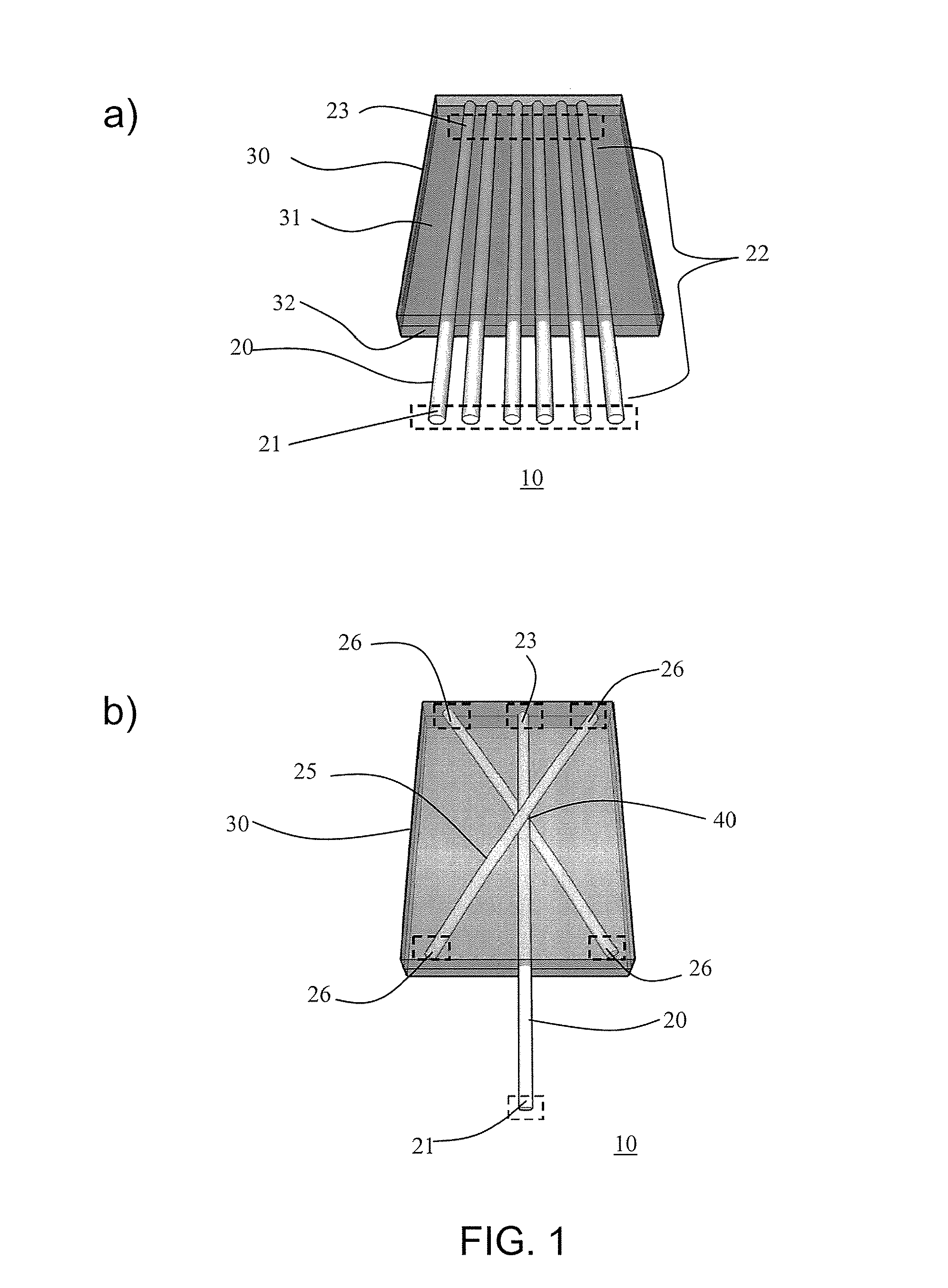
In some diagnostic systems, 100% cotton thread with a diameter of 0.3 mm was used (Cebelia Crochet Cotton Art G167, DMC, NJ, USA). This thread was of sufficient width to be enable analyte detection by the naked eye and reducing the loss of detection due to the presence of the analyte within the interior of the thread. The thread was manufactured by a process that included mercerization (exposure of a thread under tension to a NaOH bath, followed by neutralization with acid). This process increased the strength of the thread and its absorbency of water. The ability of Nylon thread (unwaxed dental floss, CVS Pharmacy Inc., RI, USA) and 100% polyester thread (McMaster-Carr, NJ, USA) to wick fluids was also tested. These artificial fibers may be well-suited for applications where transparency of the thread is needed to index-match with biological fluids.

Housings

In some of the diagnostic systems, the thread was encapsulated b...

example 2

Preparation and Use of a “Branching Array” Diagnostic System

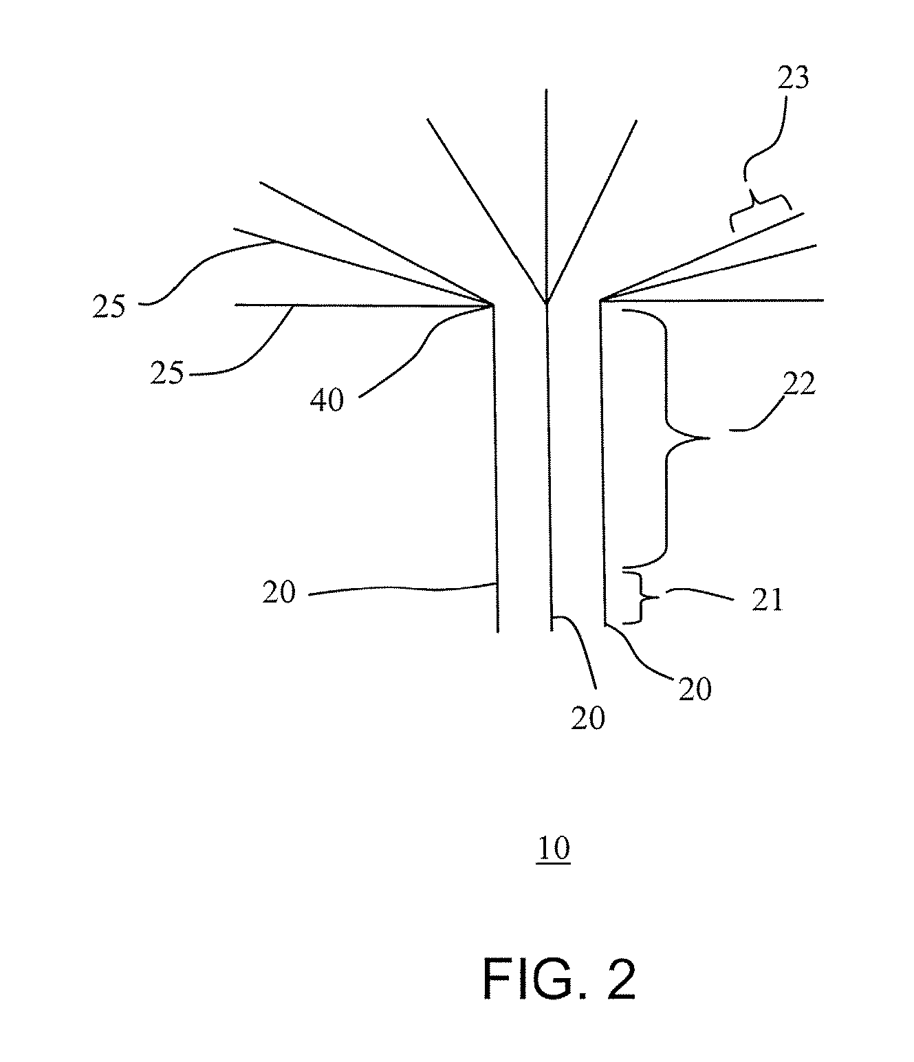
A loom as described in Example 1 was used to weave thread into a “branching array” configuration (as illustrated in FIG. 1B). The “branching array” illustrated in FIG. 1B contains only one inlet zone, which may result in smaller error rate compared to the “woven array” design. However, the “woven array” configuration may have a faster response than that of the “branching array”, because the distance from the inlet zone to the testing zone is shorter.

A branching array was used to run the colorimetric assays described in Example 1 (FIG. 9). Two factors were taken into consideration when determining the lengths of the threads for this device. First, the threads had to be long enough to prevent cross-contamination between the assays through the branching point. Second, the threads had to be longer than the distance that the diagnostic reagents traveled along the thread when preparing the testing zones.

When the detection reagent...

example 3

Preparation of a “Sewn Array” Diagnostic System

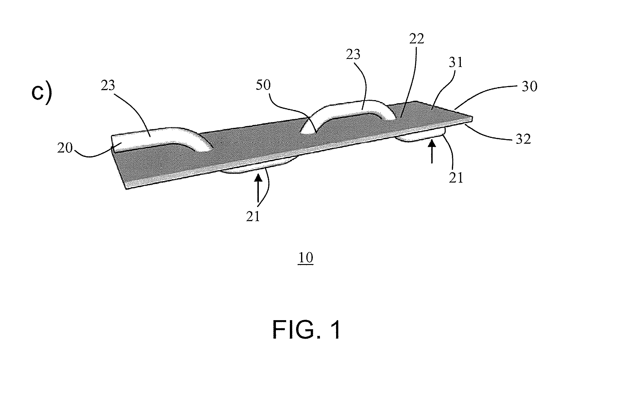
A “sewn array” diagnostic system (as illustrated in FIG. 1C) was fabricated by sewing a thread with a needle into a 0.127 mm thick Mylar strip (about 2″×6″). The assays on two adjacent stitches were physically isolated by blocking every other hole (formed by the needle) in the Mylar with 3 μL droplets of clear nail polish. Another “sewn array” was fabricated by sewing threads into an all-purpose latex free plastic bandage (CVS Pharmacy, Inc., RI), using the small holes in the bandage as guidelines for sewing the threads.

One stitch on the bottom side of the substrate and one stitch on the upper side of the substrate constitute one assay (see FIG. 1C). The lower stitch (i.e., on the bottom face of the substrate) serves as the inlet zone and the upper stitch (i.e., on the top face of the substrate) serves as the testing zone (FIG. 1C). These two stitches were defined as one unit and isolated from the other stitches by applying a 3 μL drop ...


PUM


Abstract

Hydrophilic threads as platforms for inexpensive, low volume, portable diagnostic systems, and methods of making the same are described. A diagnostic system includes a hydrophilic loading thread having an inlet zone at a proximal end; a testing zone at a distal end; and an intermediate zone located between the inlet zone and the testing zone, wherein the testing zone does not directly contact the inlet zone. In another aspect, a diagnostic system includes (i) a hydrophilic loading thread that includes an inlet zone at a proximal end and an intermediate zone at a distal end; and (ii) one or more additional hydrophilic threads that contact the intermediate zone of the loading thread. A method of detecting the presence or absence of an analyte in a fluid sample includes applying the sample to an inlet zone of a diagnostic system that includes a hydrophilic loading thread with an inlet zone at a proximal end; an intermediate zone; and a testing zone at a distal end; wherein the testing zone does not directly contact the inlet zone.

Description

BACKGROUNDMost current bioanalytical assays are inaccessible to developing economies. Current diagnostic assays typically require large and expensive laboratory instruments that are operated by trained personnel. Although “dipstick” technologies have increased the accessibility of many assays, many of the assays are too expensive for low-cost settings and often require relatively large sample volumes. Thus, there remains a need for low-cost diagnostic assays that are not cumbersome and that can be performed on small sample volumes.SUMMARYHydrophilic threads as platforms for inexpensive, low volume, portable diagnostic systems, and methods of making the same are described. Under certain aspects, the diagnostic systems are constructed by positioning hydrophilic threads within a laminated structure. This type of thread diagnostic is convenient for running low-cost, portable, and technically simple multiplexed bioassays. An illustrative embodiment is described in which the thread diagno...

Claims


Application Information

Patent Timeline
IPC IPC(8): G01N21/78C40B60/12
CPCB01L3/5088B01L2200/0605B01L2200/10B01L2300/0845B01L2300/087B01L2300/0825B01L2300/161B01L2400/0406G01N33/54386B01L3/5023B01L2300/12
Inventor RECHES, MEITALDICKEY, MICHAEL D.BUTTE, MANISH J.WHITESIDES, GEORGE M.
Owner PRESIDENT & FELLOWS OF HARVARD COLLEGE
Learn More