Throating

a technology of adhesive tape and throating, which is applied in the field of throating, can solve the problems of affecting the work efficiency of workers, and affecting the effect of construction work, so as to facilitate construction work

Active Publication Date: 2011-08-11
NICHIHA CORP
View PDF5 Cites 1 Cited by
  • Summary
  • Abstract
  • Description
  • Claims
  • Application Information

AI Technical Summary

Benefits of technology

[0015]The present invention provides a throating that enables temporary affixing and facilitates construction work.
[0016]The present invention provides a throating having a rear plate part that is fixed to a building frame, a throating plate part bent obliquely downward and frontward at a lower end of the rear plate part, and a front plate part bent downward from a front end of the throating plate part, wherein the throating has an adhesive layer on each of a front face and a rear face of the rear plate part, and has a release paper on the surface of the adhesive layers. The adhesive layers have the release paper on the surface thereof. Hence, bonding between throatings can be prevented, while preserving the adhesive performance of the adhesive layer during storage and transport. Moreover, since an adhesive layer is provided on the rear face of the rear plate part, the throating can be temporarily of to a building frame by peeling off the release paper. Further, an adhesive layer is provided also on the front face of the rear plate part, and hence a moisture-permeable waterproof sheet can be fixed to the throating by peeling the release paper during the construction work. There are two different configurations in which an adhesive layer is formed also on the top end portion of the rear plate part, and in which an adhesive layer is formed only on the front face and the rear face of the rear plate part. Configurations in which an adhesive layer is also formed on the top end portion of the rear plate part include a configuration in which the adhesive layers on the front face, the rear face and the top end portion of the rear plate part are connected to each other, a configuration in which adhesive layers are provided on the front face and the rear face of the rear plate part, such that the adhesive layers are not connected to an adhesive layer on the top end portion, and a configuration in which an adhesive layer is provided on the front face or the rear face of the rear plate part, such that the adhesive layer is not connected to an adhesive layer on the top end portion. In a case where an adhesive layer is provided only on the front face and the rear face of the rear plate part, the release papers on the front face and the rear face are connected, and cover the top end portion of the rear plate part. As a result, the top end portion of the rear plate part is constantly covered by release paper. This allows preventing the top end portion from damaging other materials, or from injuring personnel, during transport and construction.
[0018]More preferably, the cutting line is provided at a portion covering the top end portion of the rear plate part, or at a portion where the release paper covers the front face of the rear plate part, or at a portion where the release paper covers the rear face of the rear plate part. As a result, this allows peeling just the release paper that covers the adhesive layer on the rear face of the rear plate part, and hence the throating can be temporarily affixed while the adhesive layer on the front face of the rear plate part remains covered by release paper, resulting in facilitating construction work.
[0020]According to the present invention, a throating that enables temporary affixing and facilitates construction work can be provided.

Problems solved by technology

Affixing of the adhesive tape to the throating is therefore a cumbersome operation.
It is thus difficult and cumbersome, for a single operator alone, to accomplish the necessary nail driving while keeping the throating level horizontally level.
In a case where, after fixing, the fixing position of the throating is to be corrected upon noticing that the throating slants slightly, it becomes necessary to pull the nails out, correct the position of throating, and drive the nails again, all of which is cumbersome.
Moreover, throatings are manufactured through cutting and bending of a metal sheet, and hence may injure personnel or damage other materials with the cut metal sheet during transport and construction.

Method used


Image

  • Throating
  • Throating
  • Throating

Examples


Embodiment Construction

[0033]The present invention will be explained in detail below with reference to accompanying diagrams.

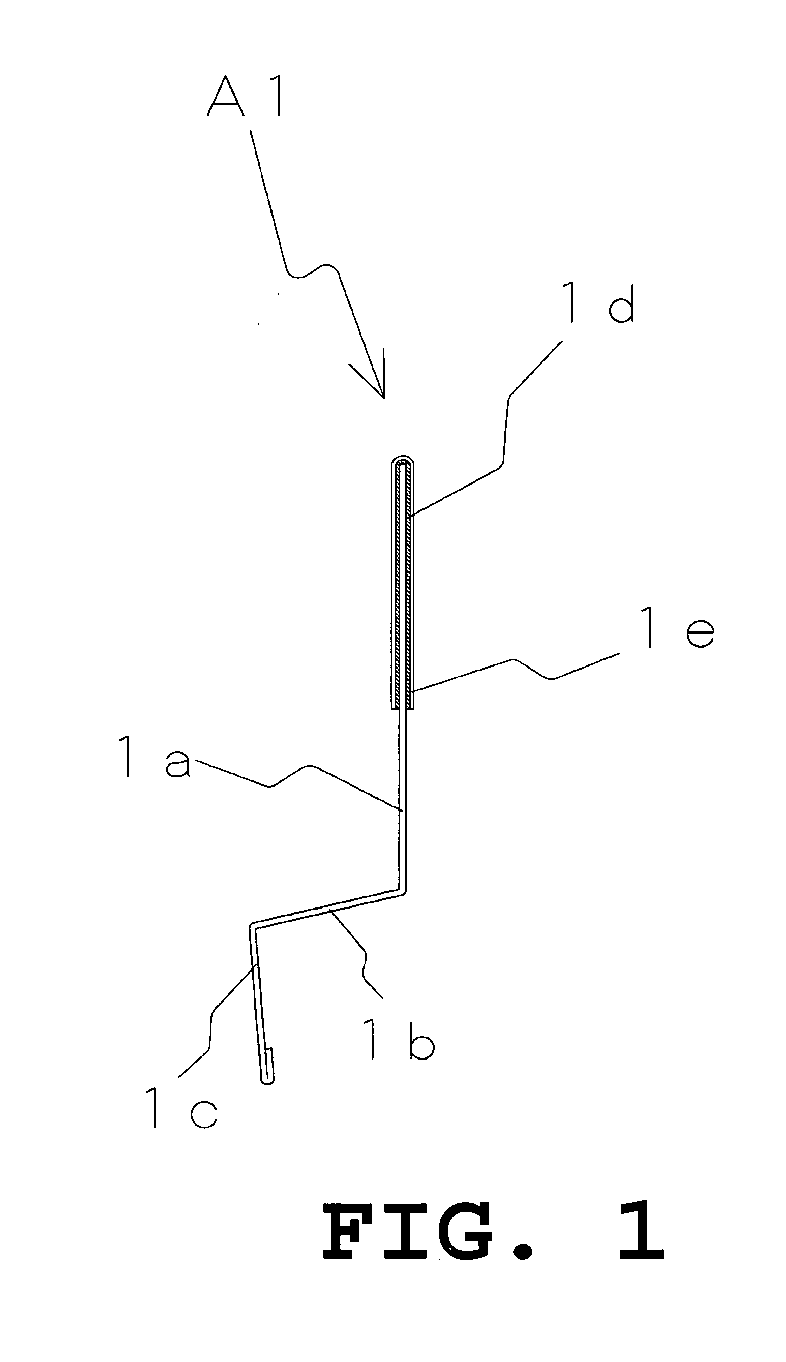
[0034]FIG. 1 is a right side-view diagram of an embodiment of a throating according to the present invention.

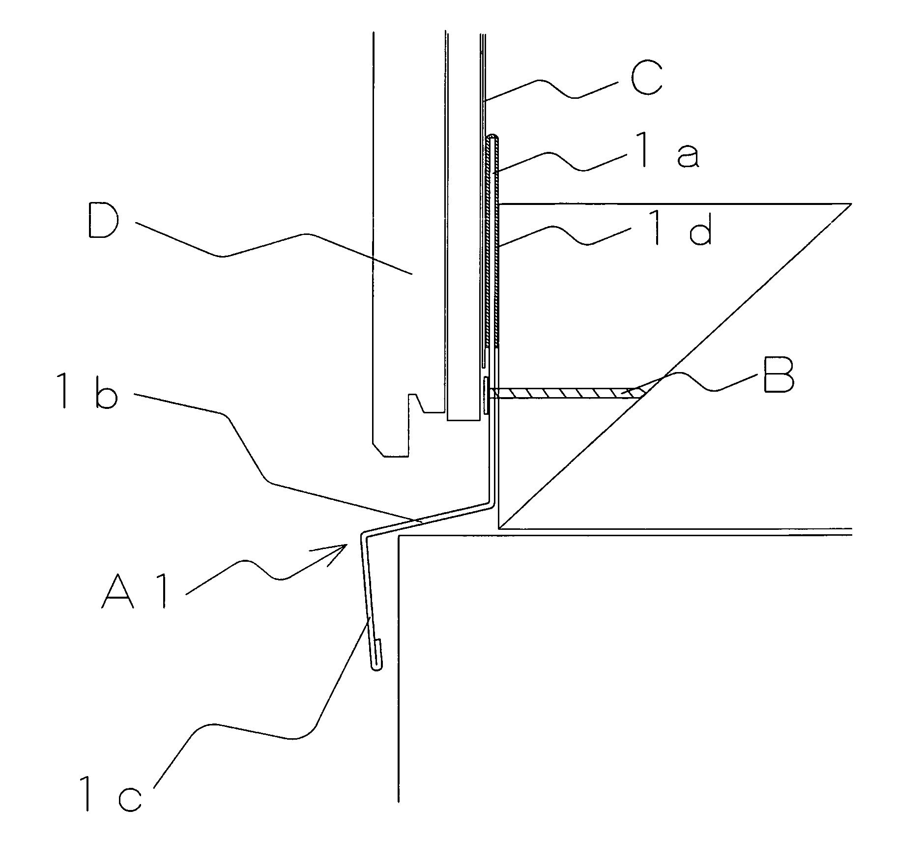
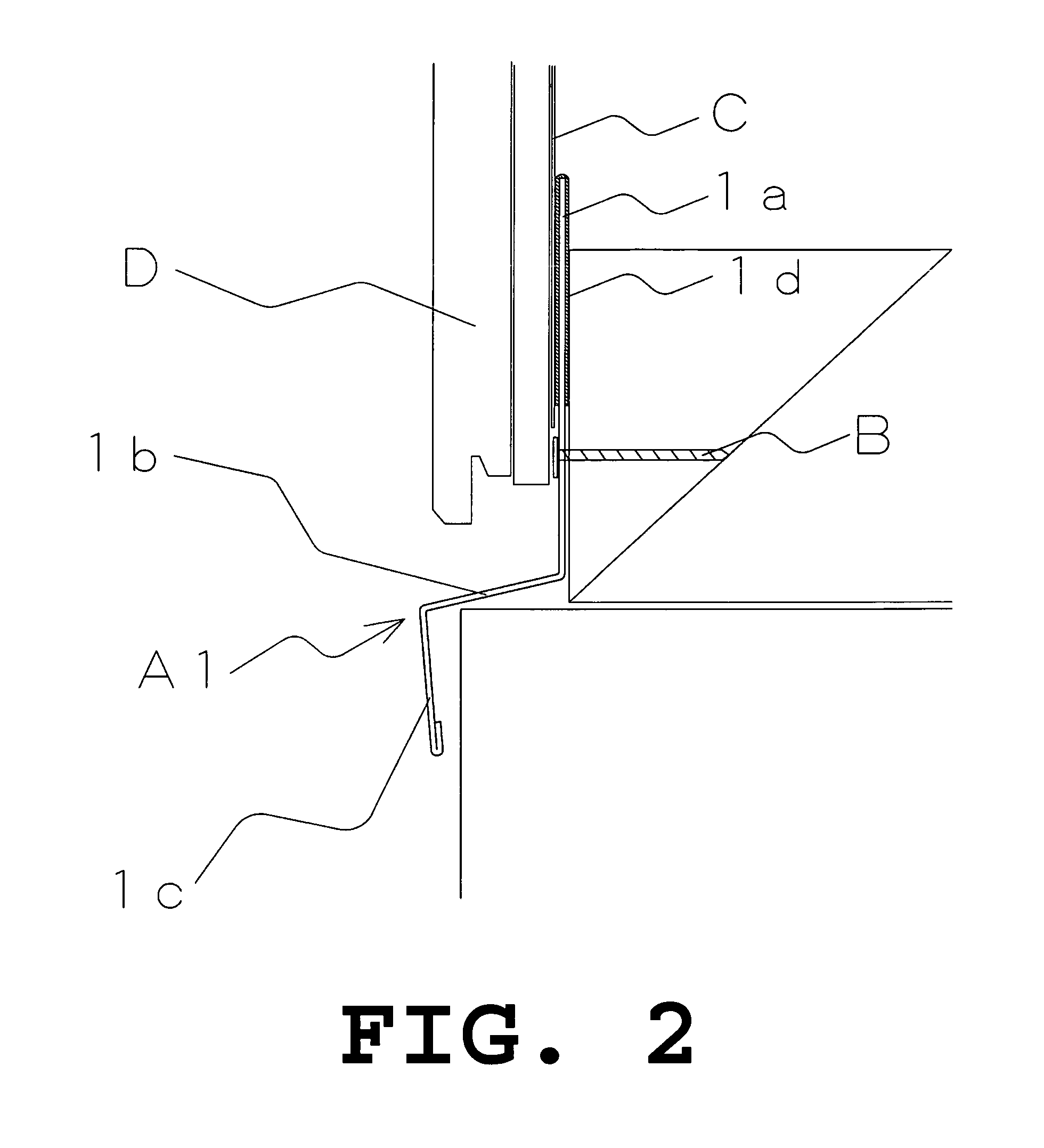
[0035]In a throating A1 illustrated in FIG. 1, which is manufactured by folding one Galvalume steel sheet, there are contiguously formed a rear plate part 1a fixed to a building frame, a throating plate part 1b bent obliquely downward and frontward at a lower end of the rear plate part 1a, and a front plate part 1c bent downward from the front end of the throating plate part 1b. More specifically, the rear plate part 1a is a flat plate part. The throating plate part 1b extends obliquely downward and frontward from the lower end of the rear plate part 1a. The front plate part 1c extends downward from the front end of the throating plate part 1b. On the front face, the top end portion and the rear face of the rear plate part 1a, an adhesive layer 1d, comprising an acrylic adhes...


PUM


Abstract

The present invention provides a throating that enables temporary affixing and facilitates construction work.The throating of the present invention includes a rear plate part that is fixed to a building frame, a throating plate part bent obliquely downward and frontward at a lower end of the rear plate part, and a front plate part bent downward from a front end of the throating plate part. The throating has an adhesive layer on each of a front face and a rear face of the rear plate part, and has a release paper on the surface of the adhesive layers. A top end portion of the rear plate part is covered by an adhesive layer and / or release paper. Preferably, the release paper has a cutting line.

Description

BACKGROUND OF THE INVENTION[0001]1. Field of the Invention[0002]The present invention relates to a throating that is fitted to a building and that drains, in a frontward direction, rainwater flowing down the surface of a siding member.[0003]2. Description of the Related Art[0004]Conventional throatings, which are manufactured through cutting and folding of a metal sheet, have an elongate shape in the horizontal direction, and are disposed, for instance, on foundation sills of buildings, or between siding boards that are disposed above and below, with a view to prevent rainwater, which flows down the outer wall of the building, from intruding into the building.[0005]For instance, Japanese Utility Model Registration No. 3031123 discloses a throating that comprises amount wall part fixed byway of nails or the like, an obliquely protruding wall part bent obliquely downward and frontward from the lower end of the mount wall part, and a protruding end wall part bent downward from the fron...

Claims


Application Information

Patent Timeline
Patent Type & Authority Applications(United States)
IPC IPC(8): E04B1/64
CPCE04D13/1478E04F19/00E06B7/26
Inventor SAWADA, YOHEIHIBINO, YOSHINORI
Owner NICHIHA CORP
Why Eureka
Try Eureka