Magnetocaloric thermal generator

a thermal generator and magnetocaloric technology, applied in the field of heat generators, can solve the problems of limited ability of this ring, high cost of material loss, and limited useful calorific output and efficiency, and achieve the effects of cost-effectiveness, improved efficiency, and simple manufacturing

Inactive Publication Date: 2011-08-11
COOLTECH APPL S
View PDF12 Cites 9 Cited by
  • Summary
  • Abstract
  • Description
  • Claims
  • Application Information

AI Technical Summary

Benefits of technology

[0008]The present invention aims to overcome these disadvantages by offering a heat generator comprising magnetocalo

Problems solved by technology

Its limits in terms of its useful calorific output and efficiency are also well known.
A first disadvantage relates to the limited ability of this ring to ensure the return of the magnetic field between two magnetized zones.
In fact, it consists of a large machined, little structured metallic mass in which the crystalline or metallurgic fibres do not exist or are oriented randomly and do not assist in the achievement

Method used


Image

  • Magnetocaloric thermal generator
  • Magnetocaloric thermal generator
  • Magnetocaloric thermal generator

Examples


Embodiment Construction

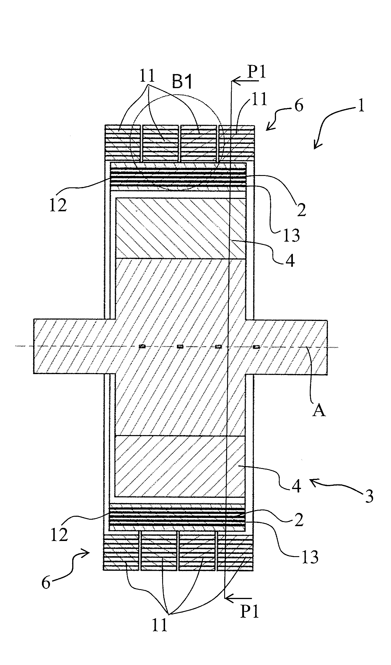
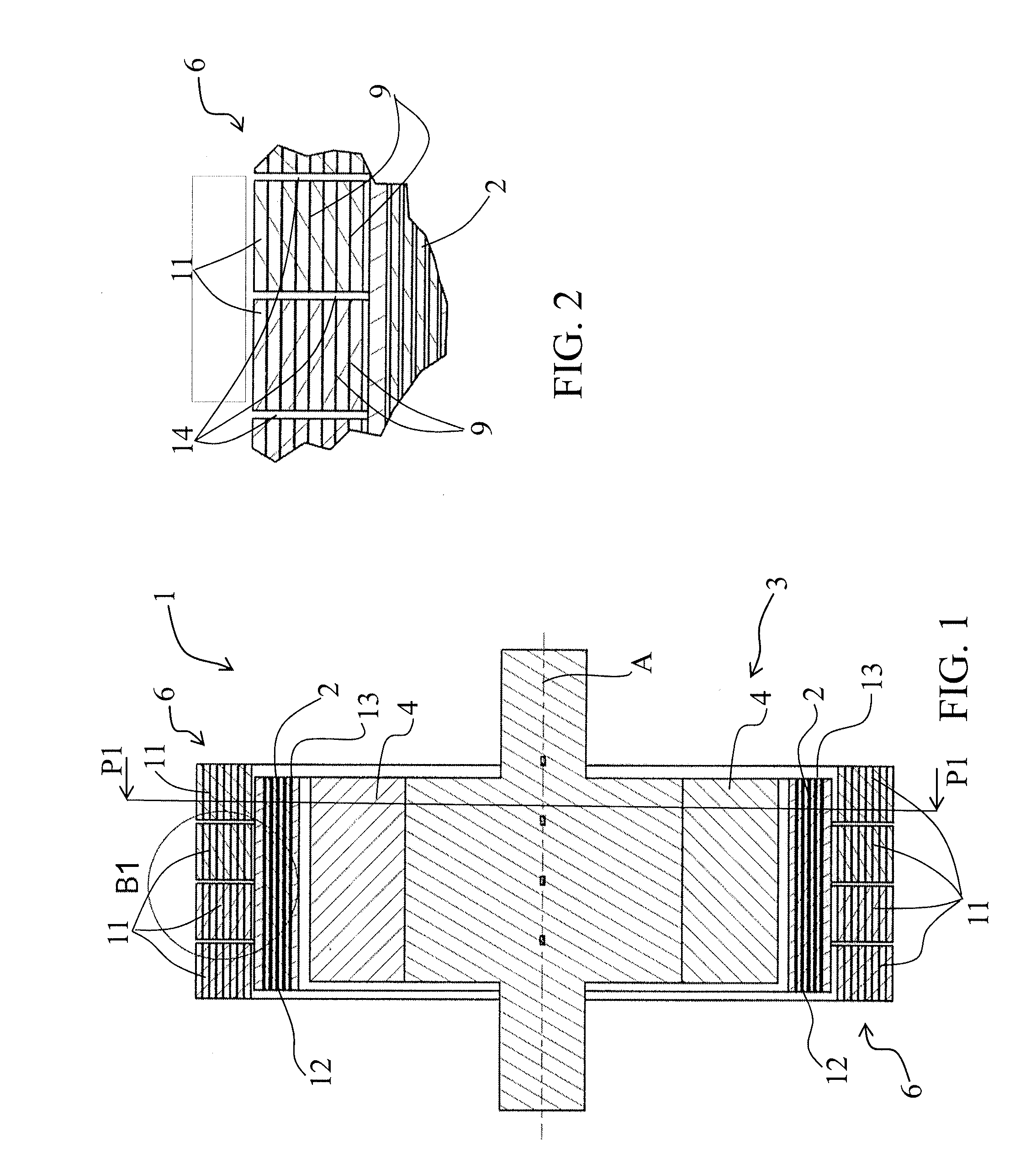
[0033]In the implementation examples shown, identical parts or sections have the same numerical references.

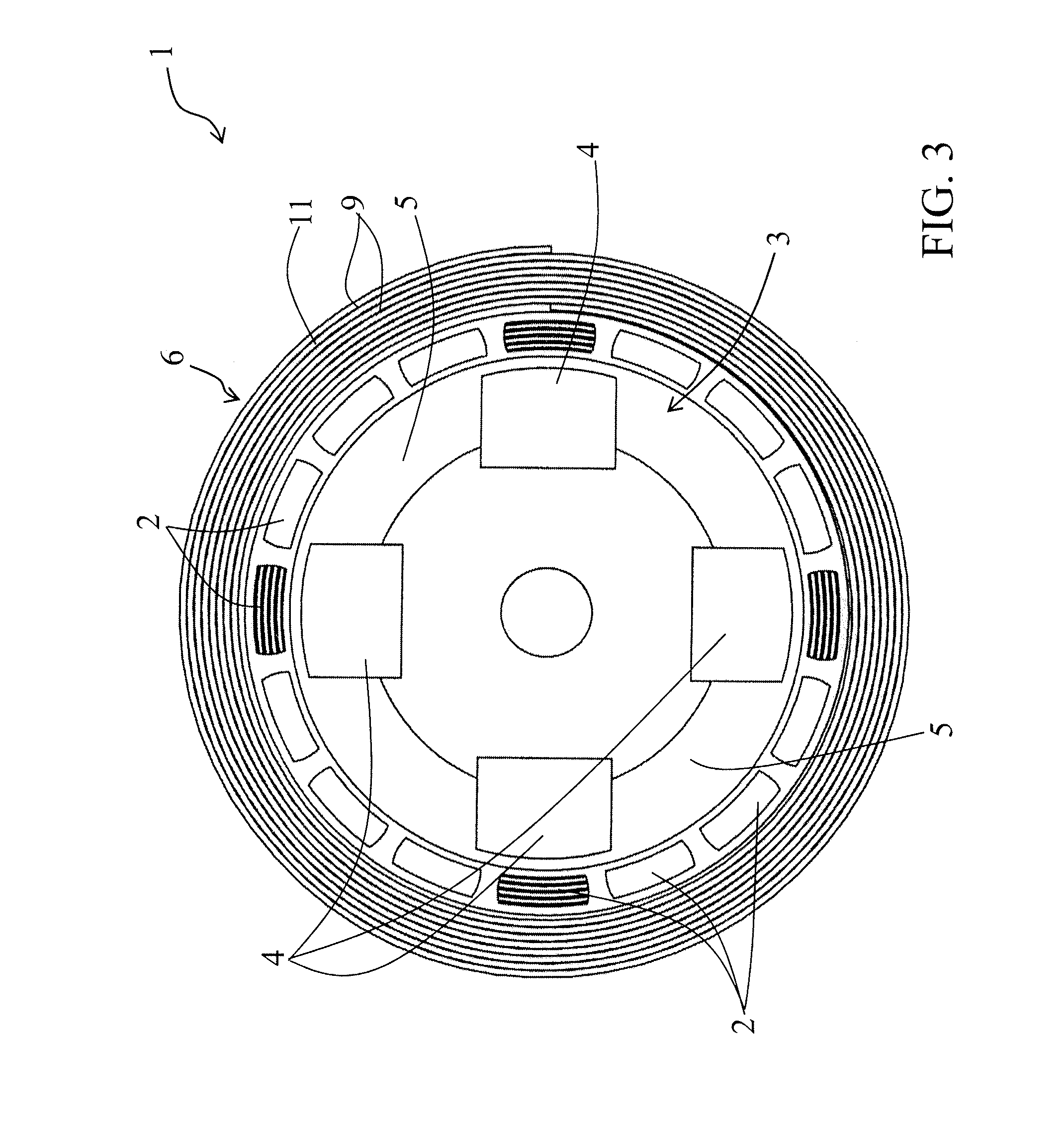
[0034]In reference to FIGS. 1, 2 and 3, the generator 1 according to the invention is made of an assembly of magnetocaloric elements 2 arranged in a circle around a central axis A.

[0035]The magnetocaloric elements 2 are subject to a magnetic field variation obtained thanks to the rotation of a magnetic arrangement 3 around the central axis A, the magnetic arrangement 3 co-operates with a field closing device 6 that is arranged to loop the magnetic flux generated by the magnetic arrangement 3. This magnetic field variation leads to the alternation of heating and cooling cycles in each magnetocaloric element 2.

[0036]The magnetic arrangement 3 comprises permanent magnets 4 that are separated from each other by an angle of 90° and have opposite polarities, which create magnetized zones 4 alternating with non magnetized zones 5. It is of course possible to choose another suitable co...


PUM


Abstract

The present invention relates to a heat generator (10) comprising magnetocaloric elements (2) arranged on a circle around a central axis, a magnetic arrangement (3) made of alternating magnetized zones (4) and non magnetized zones (5), located inside the circle formed by the magnetocaloric elements (2), rotated around the central axis and co-operating with a field closing device (6) arranged to loop the magnetic flux generated by the magnetic arrangement to subject alternately the magnetocaloric elements (2) to a magnetic field variation and create alternately in each magnetocaloric element (2) a heating cycle and a cooling cycle, in synchronization with the circulation of at least one heat transfer fluid arranged to pass through the magnetocaloric elements (2) during the heating and cooling cycles, heat generator (1) characterized in that the field closing device (6) comprises a heat insulation means (9).

Description

[0001]This application is a National Stage completion of PCT / FR2009 / 001200 filed Oct. 13, 2009, which claims priority from French patent application Ser. No. 08 / 05725 filed Oct. 16, 2008.FIELD OF THE INVENTION[0002]The present invention relates to a heat generator comprising magnetocaloric elements arranged in a circle around a central axis, a magnetic arrangement made of alternating magnetized zones and non magnetized zones, located inside of the circle formed by the magnetocaloric elements, the magnetic arrangement being rotated around the central axis and co-operating with a field closing device arranged to loop the magnetic flux generated by the magnetized zones so as to subject alternately the magnetocaloric elements to a magnetic field variation and create alternately in each magnetocaloric element a heating cycle and a cooling cycle, in synchronization with the circulation of at least one heat transfer fluid arranged to pass through the magnetocaloric elements during the heat...

Claims


Application Information

Patent Timeline
IPC IPC(8): H05B6/02
CPCF25B21/00Y02B30/66H01L37/04F25B2321/0022Y02B30/00H10N15/20
Inventor MULLER, CHRISTIANHEITZLER, JEAN-CLAUDE
Owner COOLTECH APPL S
Why Eureka
Try Eureka