
Dispenser

Inactive Publication Date: 2011-08-11
JUNG HAE RYONG
View PDF33 Cites 10 Cited by
  • Summary
  • Abstract
  • Description
  • Claims
  • Application Information

AI Technical Summary

Benefits of technology

[0014]As described above, the dispenser of the present invention has the advantage that the contents can be recharged without injecting the gas causing the explosion or the fires.
[0015]Moreover, the dispenser of the present invention has the advantage that the contents is discharged within the internal vessel to the maximum.
[0016]Moreover, the invention can improve the discharge power (draw-off force) of the contents with the compressed air which is filled between the internal vessel and the outer container. Moreover, the invention can obtain an environment friendly product which can discharge the contents with the compressed air filled between the internal vessel and the external container. And the invention can achieve the environment-friendly products to solve the above problems and most ideal products to meet the green growth project of the government, while the products, which very much comes out in the market, mixed the freon gas with the liquid gas causes harmful influence for the human body and regarded as the main cause of the greenhouse gas.BRIEF EXPLANATION OF THE DRAWINGS
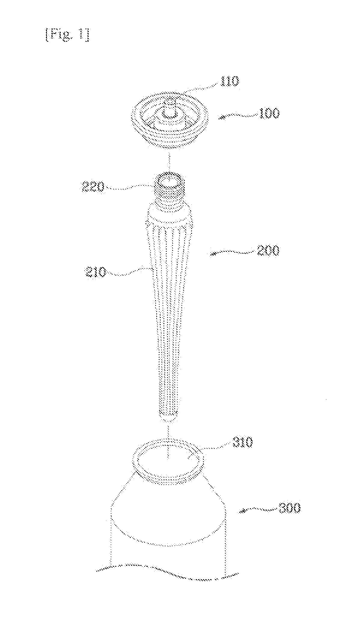
[0017]FIG. 1 is an exploded perspective view of a dispenser according to a preferred embodiment of the present invention.
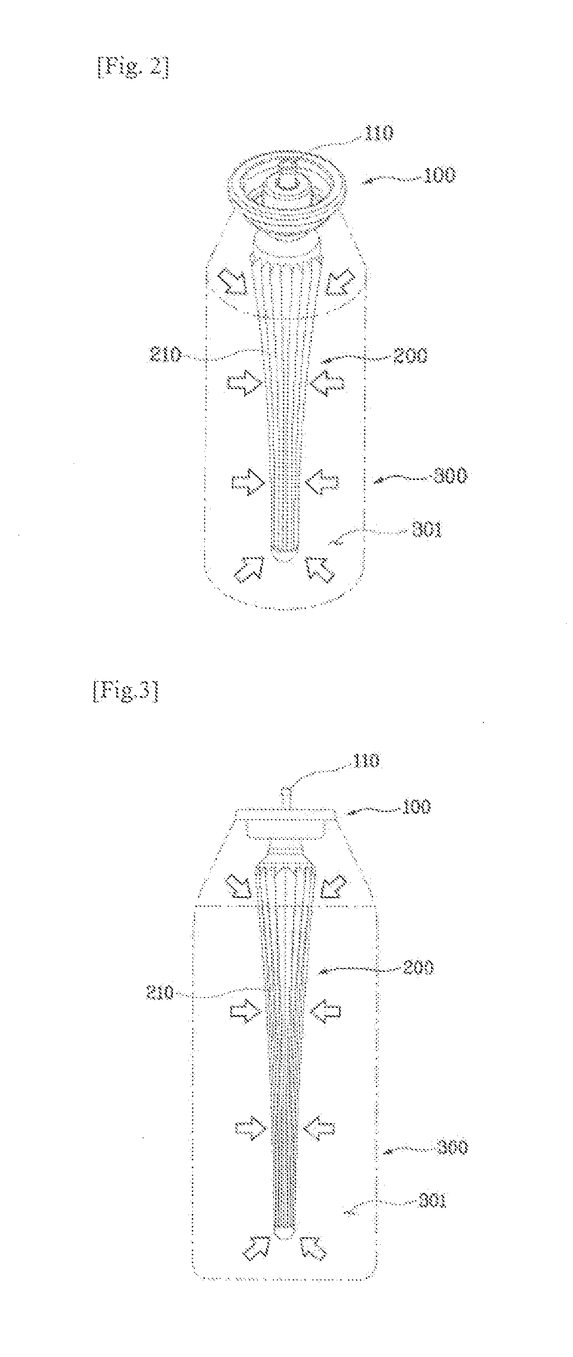
[0018]FIG. 2 is a combination perspective view of a dispenser according to a preferred embodiment of the present invention.
[0019]FIG. 3 is a front view of a dispenser according to a preferred embodiment of the present invention.

Problems solved by technology

Accordingly, the conventional dispenser still has the danger of the explosion or the fire and the harmfulness for human body, cause the environmental pollution such as the ozone layer destruction etc., and not allowing the recharge of contents.

Method used


Image

  • Dispenser
  • Dispenser
  • Dispenser

Examples


Embodiment Construction

[0025]Below, a preferred exemplary embodiment of the invention will be described in details with reference to the accompanying drawings.

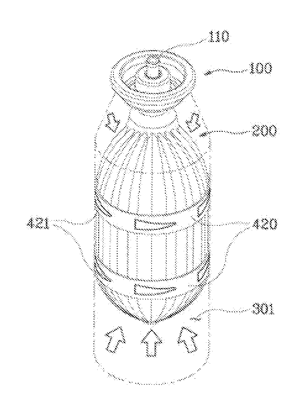
[0026]FIGS. 1 through 3 are exploded perspective view, a combination perspective view, and a front view of the dispenser according to preferred embodiments of the present invention, and show a state that the internal vessels are shrinked, and FIG. 4 is a perspective view showing a state where the internal vessel of the dispenser of FIG. 2 is swelled.

[0027]Referring to the FIGS. 1 through 4, the dispenser of the present invention comprises a plurality of pumping part (100), an internal vessel (200) and an outer container (300).

[0028]The outer container (300) has an opening onto an upper part, and a fastener (310) for coupling with the pumping part (100) is formed onto an upper part of the container.

[0029]Moreover, the outer container (300) is composed of the material in which the deformation is impossible, and a plastic of the solidity or a metal mat...


PUM


Abstract

The invention relates a dispenser comprises: an outer container (300), an internal vessel (200) for storing contents and inserted inside the outer container (300), and a pumping part (100) combined in an upper part of the internal vessel (200) and for discharging the contents in the internal vessel (200);the internal vessel is composed with a material capable of the contraction and expansion; a plurality of wrinkles (210) are formed through a blow injection manner; and the connecting rod (220) for coupling with the pumping part (100), an elastic steel band (420) formed in the outer circumference of the internal vessel (200), and a plurality of an elastic steel pieces (421) formed by cutting out a part of the steel band (420) to stand are formed onto the upper part of the internal vessel, respectively;the elastic steel piece (421) is gradually risen as the contents within the internal vessel (200) is gradually discharged, as maintaining a state where an end part reaches in contact with each other with an inner surface of the outer container (300);the contents is discharged (or exhausted) by the compressed air (301) by filling between the outer container (300) and the internal vessel (200).The dispenser further comprises a compression rubber band (410) in an outer circumference of the internal vessel (200).The dispenser further includes an elastic steel band (420) in an outer circumference of the internal vessel (200) and a plurality of elastic steel pieces (421) in which a part of the steel band (420) is cut out cut to stand, so that the elastic steel piece (421) is gradually risen as maintaining a state where an end part reaches in contact with each other with the inner surface of the outer container (300) according as the contents within the internal vessel (200) is gradually discharged.The invention is an environment friendly product which can discharge the contents with the compressed air filled between the internal vessel and the external container.And, the invention achieves environment-friendly products to solve the above problems and most ideal products to meet the green growth project of the government, while the products, which very much comes out in the market, mixed the freon gas with the liquid gas causes harmful influence for the human body and regarded as the main cause of the greenhouse gas.

Description

TECHNICAL FIELD[0001]The invention relates to a dispenser, and particularly to a dispenser which is enable to recharge contents in an internal vessel and discharge the contents within the internal vessel to the maximum.[0002]Particularly, the invention relates to the dispenser which uses the environment-friendly air harmlessing in the human body, as not using the general freon gas, to improve the discharge power (draw-off force) of contents with the compressed air which is filled between an internal vessel and an outer container.BACKGROUND ART[0003]The cosmetic of the liquid or mucoid is stored in dispenser in order to easily discharge the predetermined amounts.[0004]The dispenser includes a pumping unit installed onto an upper end of a container in which the contents is stored.[0005]As described in detail to the dispenser, the dispenser includes a nozzle formed in one side and a button for flowing out the contents through the nozzle, thereby discharging the contents, if the button ...

Claims


Application Information

Patent Timeline
IPC IPC(8): B65D35/28B67D7/60
CPCB65D83/64B65D83/62
Inventor JUNG, HAE RYONG
Owner JUNG HAE RYONG
Learn More